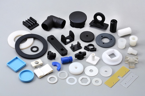
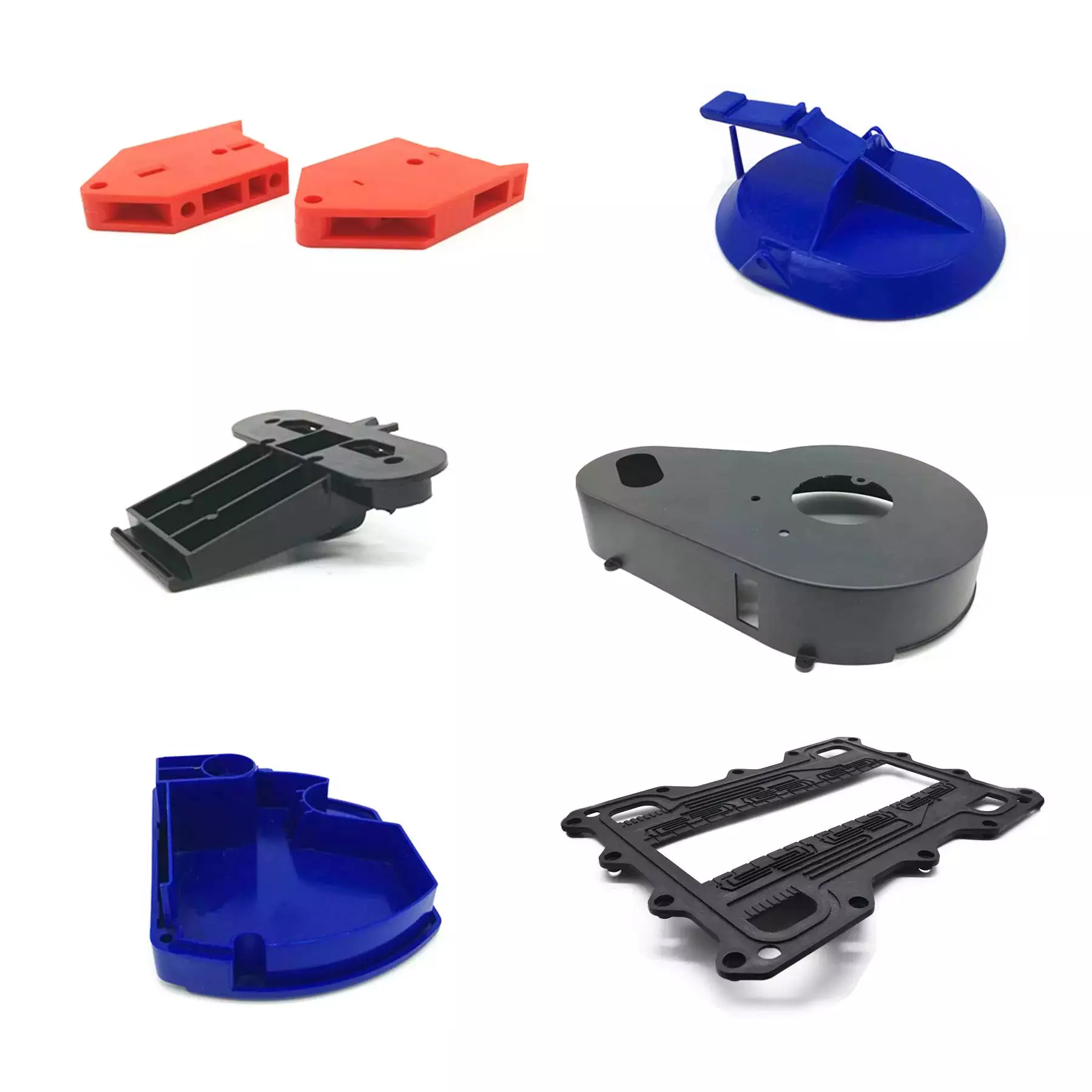
Product Description
Product Description
Basic Information
| Material | ABS, PA, PA66+30GF, PBT, PC, POM, PP, PE, MA, PVC, TPE, TPU etc |
| Color | Any color available |
| Package | Standard export carton |
| Sample Time | 5-7 working days |
| Logo | Provide Pantone color code, logo design, size |
| Design | AI, CAD, Core Draw, Original sample |
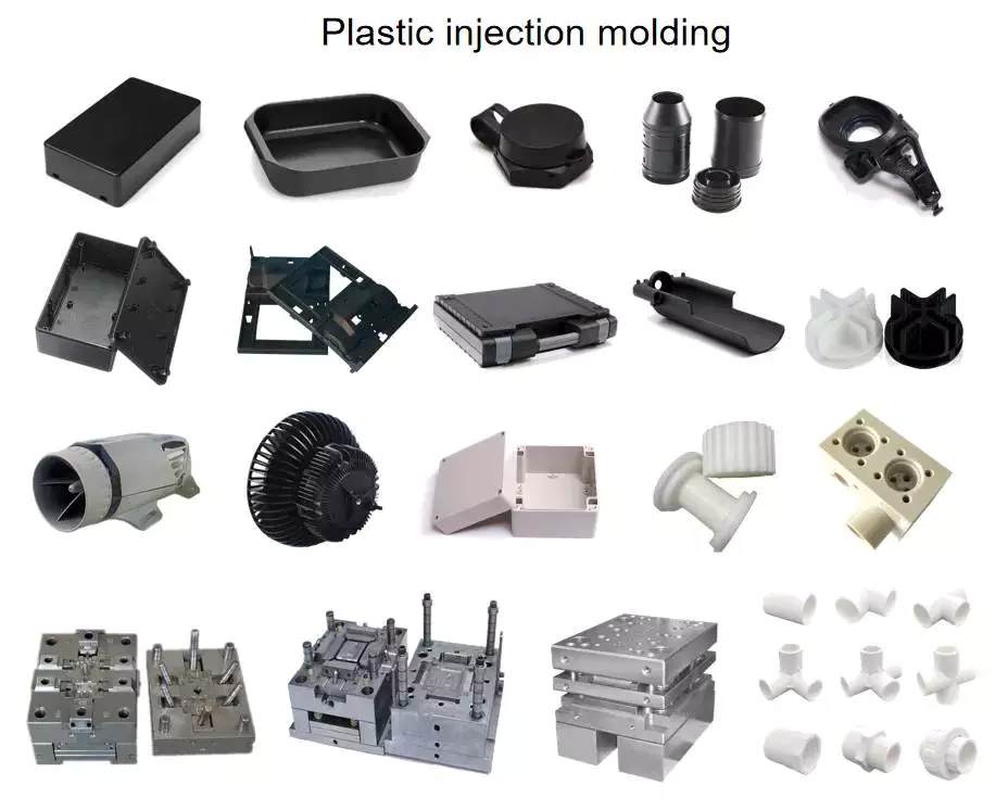
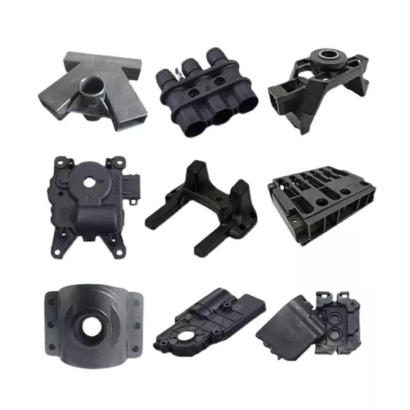
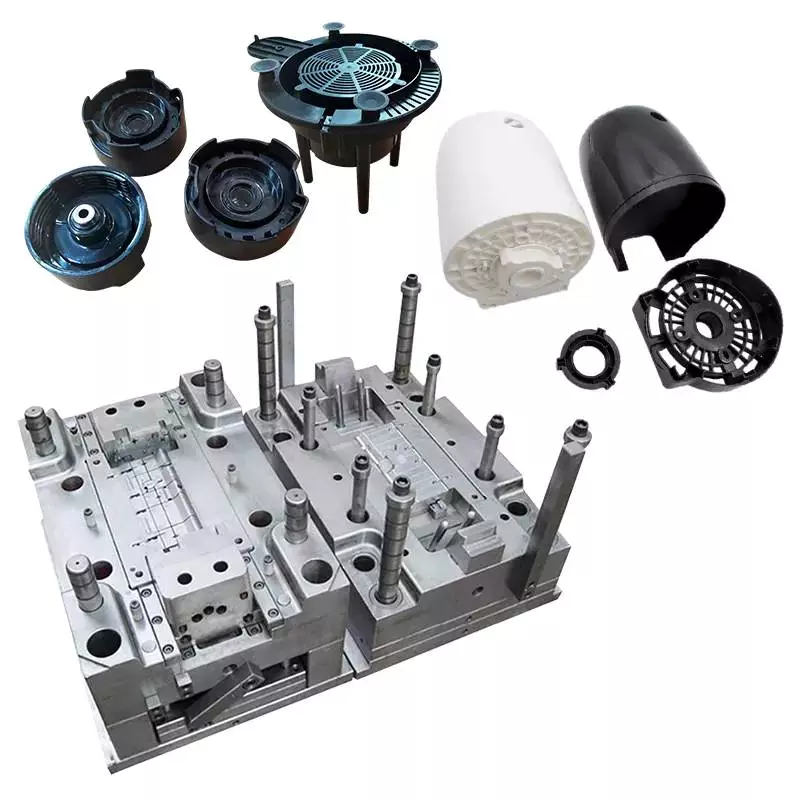
Product View:
Company Profile
FAQ
. Are you a trading company or a manufacturer?
We are a manufacturer with our own trade company.
2. What kind of trade terms can you do?
EX-WORKS, FOB, CIF, DDP, DDU
3. Do you often change the material to reduce the cost?
No, we will promise the mold quality and life, unless the customer has the request . we are
sincerely treat all customers.
4. Can you assure the quality?
Yes, We have a professional quality inspection department, the mold is strictly tested before shipment also, send the plastic product sample to you to check the mold’s quality.
5. Do you support OEM?
Yes, we can produce technical drawings or samples.
6. Can I test my idea/component before committing to mold tool manufacture?
We have a professional design team who will evaluate your requirements for design and functionality and give you an answer.
7. What type of plastic is best for my design/component?
Materials selection depends on the application of your design and the environment in which it will function. We are very glad to discuss the alternatives and give you the best suggestions.
8. How about your delivery time?
Generally, it takes 40 days ( 30 days do mold and 10 days do mass production).
| Material: | ABS |
|---|---|
| Application: | Medical, Household, Electronics, Automotive, Agricultural |
| Certification: | RoHS, ISO |
| Samples: |
US$ 1/Piece
1 Piece(Min.Order) | Order Sample |
|---|
.shipping-cost-tm .tm-status-off{background: none;padding:0;color: #1470cc}
|
Shipping Cost:
Estimated freight per unit. |
about shipping cost and estimated delivery time. |
|---|
| Payment Method: |
|
|---|---|
|
Initial Payment Full Payment |
| Currency: | US$ |
|---|
| Return&refunds: | You can apply for a refund up to 30 days after receipt of the products. |
|---|
Can you explain the role of temperature and pressure in injection molding quality control?
Temperature and pressure are two critical parameters in injection molding that significantly impact the quality control of the process. Let’s explore their roles in more detail:
Temperature:
The temperature in injection molding plays several important roles in ensuring quality control:
1. Material Flow and Fill:
The temperature of the molten plastic material affects its viscosity, or flowability. Higher temperatures reduce the material’s viscosity, allowing it to flow more easily into the mold cavities during the injection phase. Proper temperature control ensures optimal material flow and fill, preventing issues such as short shots, flow marks, or incomplete part filling. Temperature control also helps ensure consistent material properties and dimensional accuracy in the final parts.
2. Melting and Homogenization:
The temperature must be carefully controlled during the melting process to ensure complete melting and homogenization of the plastic material. Insufficient melting can result in unmelted particles or inconsistent material properties, leading to defects in the molded parts. Proper temperature control during the melting phase ensures uniform melting and mixing of additives, enhancing material homogeneity and the overall quality of the molded parts.
3. Cooling and Solidification:
After the molten plastic is injected into the mold, temperature control is crucial during the cooling and solidification phase. Proper cooling rates and uniform cooling help prevent issues such as warping, shrinkage, or part distortion. Controlling the temperature allows for consistent solidification throughout the part, ensuring dimensional stability and minimizing internal stresses. Temperature control also affects the part’s crystallinity and microstructure, which can impact its mechanical properties.
Pressure:
Pressure control is equally important in achieving quality control in injection molding:
1. Material Packing:
During the packing phase of injection molding, pressure is applied to the molten plastic material to compensate for shrinkage as it cools and solidifies. Proper pressure control ensures that the material is adequately packed into the mold cavities, minimizing voids, sinks, or part deformation. Insufficient packing pressure can lead to incomplete filling and poor part quality, while excessive pressure can cause excessive stress, part distortion, or flash.
2. Gate and Flow Control:
The pressure in injection molding influences the flow behavior of the material through the mold. The pressure at the gate, where the molten plastic enters the mold cavity, needs to be carefully controlled. The gate pressure affects the material’s flow rate, filling pattern, and packing efficiency. Optimal gate pressure ensures uniform flow and fill, preventing issues like flow lines, weld lines, or air traps that can compromise part quality.
3. Ejection and Part Release:
Pressure control is essential during the ejection phase to facilitate the easy removal of the molded part from the mold. Adequate ejection pressure helps overcome any adhesion or friction between the part and the mold surfaces, ensuring smooth and damage-free part release. Improper ejection pressure can result in part sticking, part deformation, or mold damage.
4. Process Monitoring and Feedback:
Monitoring and controlling the temperature and pressure parameters in real-time are crucial for quality control. Advanced injection molding machines are equipped with sensors and control systems that continuously monitor temperature and pressure. These systems provide feedback and allow for adjustments during the process to maintain optimum conditions and ensure consistent part quality.
Overall, temperature and pressure control in injection molding are vital for achieving quality control. Proper temperature control ensures optimal material flow, melting, homogenization, cooling, and solidification, while pressure control ensures proper material packing, gate and flow control, ejection, and part release. Monitoring and controlling these parameters throughout the injection molding process contribute to the production of high-quality parts with consistent dimensions, mechanical properties, and surface finish.
What is the role of design software and CAD/CAM technology in optimizing injection molded parts?
Design software and CAD/CAM (Computer-Aided Design/Computer-Aided Manufacturing) technology play a crucial role in optimizing injection molded parts. They provide powerful tools and capabilities that enable designers and engineers to improve the efficiency, functionality, and quality of the parts. Here’s a detailed explanation of the role of design software and CAD/CAM technology in optimizing injection molded parts:
1. Design Visualization and Validation:
Design software and CAD tools allow designers to create 3D models of injection molded parts, providing a visual representation of the product before manufacturing. These tools enable designers to validate and optimize the part design by simulating its behavior under various conditions, such as stress analysis, fluid flow, or thermal performance. This visualization and validation process help identify potential issues or areas for improvement, leading to optimized part designs.
2. Design Optimization:
Design software and CAD/CAM technology provide powerful optimization tools that enable designers to refine and improve the performance of injection molded parts. These tools include features such as parametric modeling, shape optimization, and topology optimization. Parametric modeling allows for quick iteration and exploration of design variations, while shape and topology optimization algorithms help identify the most efficient and lightweight designs that meet the required functional and structural criteria.
3. Mold Design:
Design software and CAD/CAM technology are instrumental in the design of injection molds used to produce the molded parts. Mold design involves creating the 3D geometry of the mold components, such as the core, cavity, runner system, and cooling channels. CAD/CAM tools provide specialized features for mold design, including mold flow analysis, which simulates the injection molding process to optimize mold filling, cooling, and part ejection. This ensures the production of high-quality parts with minimal defects and cycle time.
4. Design for Manufacturability:
Design software and CAD/CAM technology facilitate the implementation of Design for Manufacturability (DFM) principles in the design process. DFM focuses on designing parts that are optimized for efficient and cost-effective manufacturing. CAD tools provide features that help identify and address potential manufacturing issues early in the design stage, such as draft angles, wall thickness variations, or parting line considerations. By considering manufacturing constraints during the design phase, injection molded parts can be optimized for improved manufacturability, reduced production costs, and shorter lead times.
5. Prototyping and Iterative Design:
Design software and CAD/CAM technology enable the rapid prototyping of injection molded parts through techniques such as 3D printing or CNC machining. This allows designers to physically test and evaluate the functionality, fit, and aesthetics of the parts before committing to mass production. CAD/CAM tools support iterative design processes by facilitating quick modifications and adjustments based on prototyping feedback, resulting in optimized part designs and reduced development cycles.
6. Collaboration and Communication:
Design software and CAD/CAM technology provide a platform for collaboration and communication among designers, engineers, and other stakeholders involved in the development of injection molded parts. These tools allow for easy sharing, reviewing, and commenting on designs, ensuring effective collaboration and streamlining the decision-making process. By facilitating clear communication and feedback exchange, design software and CAD/CAM technology contribute to optimized part designs and efficient development workflows.
7. Documentation and Manufacturing Instructions:
Design software and CAD/CAM technology assist in generating comprehensive documentation and manufacturing instructions for the production of injection molded parts. These tools enable the creation of detailed drawings, specifications, and assembly instructions that guide the manufacturing process. Accurate and well-documented designs help ensure consistency, quality, and repeatability in the production of injection molded parts.
Overall, design software and CAD/CAM technology are instrumental in optimizing injection molded parts. They enable designers and engineers to visualize, validate, optimize, and communicate designs, leading to improved part performance, manufacturability, and overall quality.
Are there different types of injection molded parts, such as automotive components or medical devices?
Yes, there are various types of injection molded parts that are specifically designed for different industries and applications. Injection molding is a versatile manufacturing process capable of producing complex and precise parts with high efficiency and repeatability. Here are some examples of different types of injection molded parts:
1. Automotive Components:
Injection molding plays a critical role in the automotive industry, where it is used to manufacture a wide range of components. Some common injection molded automotive parts include:
- Interior components: Dashboard panels, door handles, trim pieces, instrument clusters, and center consoles.
- Exterior components: Bumpers, grilles, body panels, mirror housings, and wheel covers.
- Under-the-hood components: Engine covers, air intake manifolds, cooling system parts, and battery housings.
- Electrical components: Connectors, switches, sensor housings, and wiring harnesses.
- Seating components: Seat frames, headrests, armrests, and seatbelt components.
2. Medical Devices:
The medical industry relies on injection molding for the production of a wide range of medical devices and components. These parts often require high precision, biocompatibility, and sterilizability. Examples of injection molded medical devices include:
- Syringes and injection pens
- Implantable devices: Catheters, pacemaker components, orthopedic implants, and surgical instruments.
- Diagnostic equipment: Test tubes, specimen containers, and laboratory consumables.
- Disposable medical products: IV components, respiratory masks, blood collection tubes, and wound care products.
3. Consumer Products:
Injection molding is widely used in the production of consumer products due to its ability to mass-produce parts with high efficiency. Examples of injection molded consumer products include:
- Household appliances: Television and audio equipment components, refrigerator parts, and vacuum cleaner components.
- Electronics: Mobile phone cases, computer keyboard and mouse, camera components, and power adapters.
- Toys and games: Action figures, building blocks, puzzles, and board game components.
- Personal care products: Toothbrushes, razor handles, cosmetic containers, and hairdryer components.
- Home improvement products: Light switch covers, door handles, power tool housings, and storage containers.
4. Packaging:
Injection molding is widely used in the packaging industry to produce a wide variety of plastic containers, caps, closures, and packaging components. Some examples include:
- Bottles and containers for food, beverages, personal care products, and household chemicals.
- Caps and closures for bottles and jars.
- Thin-walled packaging for food products such as trays, cups, and lids.
- Blister packs and clamshell packaging for retail products.
- Packaging inserts and protective foam components.
5. Electronics and Electrical Components:
Injection molding is widely used in the electronics industry for the production of various components and enclosures. Examples include:
- Connectors and housings for electrical and electronic devices.
- Switches, buttons, and control panels.
- PCB (Printed Circuit Board) components and enclosures.
- LED (Light-Emitting Diode) components and light fixtures.
- Power adapters and chargers.
These are just a few examples of the different types of injection molded parts. The versatility of injection molding allows for the production of parts in various industries, ranging from automotive and medical to consumer products, packaging, electronics, and more. The specific design requirements and performance characteristics of each part determine the choice of materials, tooling, and manufacturing processes for injection molding.


editor by CX 2023-11-21
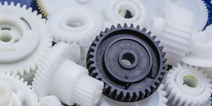
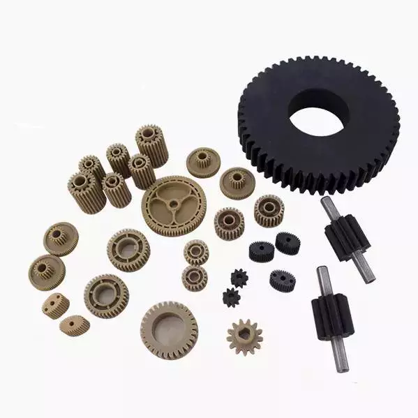
China pa66 gf30 PEEK oem custom transparent large small precision gear medical device plastic part injection auto components parts injection molded car parts
Model Quantity: pa66 gf30 PEEK
Shaping Manner: Plastic Injection Mould
Item Content: PP, Abdominal muscles, PVC, PE…
Merchandise: ALL
Materials: PP, Abs, PVC, PE…
Size: Personalized Dimension
Method: Injection
Tolerance: .~500000shots
Shipping and delivery Time: twenty five-40days
Packaging Information: OPP bag, carton, Pallet
Port: HangZhou or ZheJiang ,China
| Product Parameters | ||||||||
| Quotation | According to your drawing(dimension, materials, thickness, processing content, and needed technological innovation, and so on) | |||||||
| Available Materials | Brass, stainless metal, copper, aluminum alloy and so on. | |||||||
| More Processing | CNC Machining,Plastic Injection,Stamping,Die Casting,Welding,Forging,Silicone And Rubber,Mould Producing,and many others | |||||||
| Surface Remedy | Powder Coating, Anodizing, Brushing, Sharpening, Electric powered-plating, Pvd Coating, Hot Dip Galvanizing, E-coating, Tin Plating,Nickel,Plating, Chrome Plating, Dacromet, Enamel Coating etc. | |||||||
| OEM | Silkscreening, OEM Factory Customized Made Substantial Precision Mold Plastic Nylon Digital Undertaking Injection Electrical Plug Go over Housings Elements Engraving,Laser Printing,Reduce-out generating, Customized Packaging Box and so forth. | |||||||
| Application | All sorts of cars,machinery,residence equipment,digital items,electrical equipment,stationery,computer systems,power switches,miniatureswitcher,architecture,commodity and A/V gear,components and plastic molds,athletics gear and items,and a lot more. | |||||||
| Manufacturing Kind | Precision Machining, CNC Milling, CNC Lathe Turning, Tapping, Drilling, Grinding, Wie EDM, Stamping, Deep Drawing, CNC Punching,Laser Chopping, CNC Bending, Die Casting, Welding etc | |||||||
| Industries Served | Aerospace, Automotive, Agriculture, Building, Electrical, Electronic, Property Appliance, Healthcare,Marine, Machinery, Injection Molded Areas Manufacturing unit Customized Solid CZPT Plastic Tooling Home furniture,Foods, Lights,Telecommunication and many others | |||||||
| File Format | Solidworks,Professional/Engineer,Automobile CAD,PDF,JPG,DXF,IGS,Stage | |||||||
| QC | 100% Strict Inspection For Each Processing | |||||||
| One-end Services | Custom Layout, Fabrication, Assembly And Shipping and delivery | |||||||
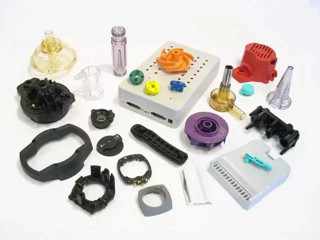
Design Considerations for Injection Molded Parts
There are many factors to consider when designing a component for injection molding. These include design factors, materials, overhangs, and process. Understanding these factors will make it easier to choose the right part for the application. In this article, we’ll go over several of the most common design considerations.
Design factors
 To get the best results from your injection molded parts, you must ensure that they meet certain design factors. These factors can help you achieve consistent parts and reduce cost. These guidelines can also help you to avoid common defects. One of the most common defects is warping, which is caused by the unintended warping of the part as it cools.
When designing injection molded parts, the draft angle is critical. Increasing the draft angle allows the part to emerge cleanly from the mold and reduces stress concentration. This can improve the part’s function and speed up the production process. In addition, it ensures a uniform surface finish. Incorrect draft angles can result in parts that are not functional and can cost you money. If your product team doesn’t pay attention to these design factors, they could end up destroying expensive molds and producing a high number of rejects.
Ribs are another design factor that should be taken into consideration. Rib height should be less than three times the thickness of the part’s wall. This will prevent sink marks and minimize the chances of the ribs sticking inside the mold.
Materials
There are many options when it comes to materials for injection molded parts. Choosing the right material will affect how well it performs in your particular application. If you need a large part to be flexible and sturdy, then a plastic with good flow properties will work best. Injection molded plastics come in a variety of different resins. Choose the one that best meets your application’s needs, considering its main functionality and the desired appearance. You may also want to choose a material that is UV resistant, heat resistant, flexible, and food safe.
Polymers that are suitable for injection molding include polycarbonate and polypropylene. These materials are flexible and strong, and can be used to create parts with high-level details. These materials are also lightweight and inexpensive. Despite being flexible, they are not suitable for high-stress applications.
During the molding process, the injected material must be cooled, otherwise it will expand again. This is why you need to keep the temperature of the mould at 80 degrees Celsius or less.
Process
Injection molding is the process of creating plastic parts. The plastic is melted in a mold and then forced to cool. It then solidifies into the desired shape. During the cooling process, the plastic can shrink, so it is important to pack the material tightly in the mold to prevent visible shrinkage. When the mold is completed, it cannot be opened until the required cooling time has passed. This time can be estimated based on the thermodynamic properties of plastic and the maximum wall thickness of the part.
The mold must be precisely designed and tested. The process can be repeated many times, which makes it ideal for mass production. It is also one of the fastest ways to scale production. The more parts a mold can produce, the lower its cost per piece. This is one of the benefits of injection molding.
Injection molding parts are used for many industries, including appliances, electronics, packaging, and medical devices. They can be made to have complicated shapes.
Overhangs
 Overhangs are areas of extra material that surround the surface of an injection molded part. This extra material is typically made of inexpensive material that is edged or glued on the part’s surface. The overhang material can be easily separated from the blank using a simple cutting process.
The amount of material needed for an overhang is dependent on the shape of the part and the amount of surface area. Generally, an overhang is less than 15 percent of the cost of the part. Usually, the material used should be able to fulfill the overhang’s function and differentiate it from the material in the form flachen area.
Overhangs on injection molded parts should be avoided because they may cause the design to become unstable. To avoid this problem, consider designing your part so that the sides and edges are parallel to one another. This will help ensure that the part will be free of undercuts and overhangs.
Overhangs on injection molded parts can be avoided by ensuring that the parts are designed with tolerances in mind. For example, an overhang in an injection molded part can cause a mold to have an overhang that is too small for the machine. This can cause problems in the manufacturing process, and it can result in a costly mold.
Cost
Injection molding costs can vary depending on the complexity of the part, the size and the type of plastic. Parts with complex geometries may require additional design work and tooling. Larger parts can also cost more than small ones. The amount of time spent designing and producing them is also important.
To reduce the cost of injection molding, a manufacturer must consider two major factors: tooling and the material used. The plastic used for injection molding has several different properties, which will impact the part price. For instance, plastics with a lot of glass fibers will reduce the amount of time necessary to repair the mold. Another factor to consider is the thermal properties of the material.
The next major factor in the cost of injection molded parts is the material of the injection mold. While most of these molds are made of steel, the type and grade of steel used is important. Injection molds are also required to have nearly wear-free interior cavities. This is necessary to maintain tight tolerances.
Another factor that contributes to the cost of injection molded parts is the cost of bulk material. This material costs money and requires expensive electricity to process. Typically, the more parts you produce, the lower the cost per pound. Storage of bulk material is also a significant expense. Therefore, a quicker cycle time will reduce storage costs.
Reliability
While manufacturing involves some degree of variation, the variation should be within acceptable limits. This is essential if you want to produce high-quality, dimensionally stable parts. A reliable manufacturing process involves precise control over mold tooling and part design. It also requires repeatability in both quality and production processes.
A reliable injection molding process also focuses on detecting defects early in the production process. Invisible hazards, such as air pockets, mold materials compromised by overheating, and more, can lead to failure. These defects will most likely not be discovered by simple visual inspection and may not come to light until after warranty claims are filed from the field. By finding the defects in the early stages, manufacturers can maximize productivity and reduce costs by minimizing the number of replacement parts needed.
The process of building a custom mould for plastic components is highly skilled. A perfect mould will eliminate potential defects and ensure that the production process is reliable. Traditionally, this process relied on trial and error, which added time and money to the production process.
Design for manufacturability
 When designing injection molded parts, it is imperative to keep in mind their manufacturability. Injection molding allows for complex geometries and multiple functions to be combined into a single part. For example, a hinged part can have a single mold that can produce two different halves. This also decreases the overall volume of the part.
Injection molded parts do not typically undergo post-processing. However, the mold itself can be finished to various degrees. If the mold is rough, it can cause friction during the ejection process and require a larger draft angle. Detailed finishing procedures are outlined by the Society of Plastics Industry.
The process of designing injection molds is very exacting. Any errors in the mold design can lead to out-of-spec parts and costly repair. Therefore, the process of Design for Manufacturability (DFM) validation is a key step early in the injection molding process. Fictiv’s DFM feedback process can identify design challenges and provide early feedback to minimize lead times and improve quality.
The surface of an injection molded part can develop sink marks, which occur when the material has not fully solidified when it is ejected from the mold. Parts with thick walls or ribs are more prone to sinking. Another common defect in plastic injection molding is drag marks, which occur when walls scrape against one another during ejection. In addition to sink marks, parts with holes or exposed edges can form knit lines.
editor by czh2023-02-15
China Custom Rubber Bonded to Metal Gear Parts/Transmission Gear/ with Good quality
Product Description
Custom made Rubber Bonded to gear parts
one)Custom manufactured Rubber to Steel Gear Bonded Elements
2)Various colours and design for every your ask for
three)Aggressive cost, Large top quality
We supply Rubber to Steel Bonded Parts like dampers, anti-vibration mountings, wheels & rollers and many others.
Rubber and metallic bonded components which includes: Absorber, damper bushing, grommet, spring plate, cable protect.
* Industries: Automotive Sanitary Furnishings.
* Content: Silicone, Viton, EPDM, Neoprene, Natural Rubber and many others. For each your ask for
* Traits: Higher temperature resistance, oil resistance, abrasion resistance, getting older resistance, corrosion resistance, and so on.
The introduction of our firm
one. Equipped with present day and exact manufacture equipments and strictly good quality handle which permit us to make large quality vehicle elements
2.Higher efficient management to attain the production price optimization, and return the profit to consumer end for prolonged term get acquire connection.
Unimolding Main Aggressive Advantages:
one.Consumer-targeted organization
2.Smooth & fast communication
three.Personalized manufacturing & Engineering solution
4.Superb good quality handle
five.Affordable price
six.Small order & on-time supply
7.Perform the teamwork exercise.
The deal of our products
| To Be Negotiated | 500 Pieces (Min. Order) |
###
| Hardness: | According to Requirement |
|---|---|
| Material: | Silicone, Viton, EPDM, Neoprene, Natural Rubber Et |
| Software for Drawings: | Auto CAD, PRO-E, Ug, Solid Work, Catia, etc. |
| Processing: | Rubber Injection, Rubber Molded |
| Temperature: | -40c-240c( or Per Your Required) |
| Industries: | Automotive; Sanitary; Furniture |
###
| Samples: |
US$ 1.00/Piece
1 Piece(Min.Order) |
|---|
###
| Customization: |
Available
|
|---|
Advantages of Injection Moulding
Whether you’re considering an injection molded part for your next project or need to replace an existing one, there are a few factors you should consider. These include design, surface finishes, tooling costs, and material compatibility. Understanding these factors can help you make the right decision. Read on to learn more about the advantages of injection molding and how to get started.
Design factors
 One of the most critical design factors for injection molded parts is the wall thickness. The wall thickness affects many key characteristics of the part, from its surface finish to its structural integrity. Proper consideration of this factor can prevent costly delays due to mold issues or mold modifications. To avoid this problem, product designers must carefully consider the functional requirements of the part to determine the minimum and nominal wall thickness. In addition, they must also consider acceptable stress levels, since parts with excessively thin walls may require excessive plastic pressure and may create air traps.
Another factor to consider when designing a part is its ejection and release capabilities. If the part is released from the mold, the tools should be able to slide the plastic out. Injection molds usually have two sides, one of which is ejectable, and another that remains in the mold. In some cases, special features are required to prevent part release, such as a ramp or a gusset. These design features can increase the design flexibility, but they can also increase the cost of the mold.
When designing injection molded parts, the engineering team first determines the key design elements. These elements will make sure the injection process goes as smoothly as possible. This includes factors like wall thickness, rib design, boss design, corner transition, and weld line, among others. The engineering team will then perform a design for manufacturability analysis and, if all is well, can start building and testing the mold.
Material compatibility
Several factors can affect material compatibility of injection molded parts. When molding plastic parts, it is important to choose a material that is compatible with the part’s intended purpose. Many injection molding processes require that the two main plastic materials used are compatible with each other. This is the case in overmolding and two-shot injection molding.
The material you use to make an injection molded part will significantly impact the tolerance of the finished product. This is why material selection is as important as the design of the part. Many types of plastic resins can be used for injection molding. In addition, many of these resins can be modified or strengthened by adding additives, fillers, and stabilizers. This flexibility allows product teams to tailor the material to achieve desired performance characteristics.
One of the most common thermoplastics is polypropylene. It is extremely durable and has good impact strength and moisture resistance. This material is also recyclable and does not react with food.
Tooling costs
One of the largest costs for manufacturing injection molded parts is tooling. For an OEM, tooling costs can range from $15K per part for a simple part to $500K for a mold with complex geometry. Tooling costs vary based on the type of steel used and the production volume of the part.
To get a reasonable estimate, companies should have a final design, preliminary design, and sample part to hand when requesting quotes. The dimensions and complexity of the cavity in a mold are crucial in determining the tooling cost, as are the part tolerances. Part tolerances are based on the area covered by the part and its functions within the mold.
The type of mold you need can also impact your tooling costs. Injection molding machines can accommodate many different kinds of molds. Some molds are made from a single mold, while others require multiple molds. Some molds can be complicated, making them unmanufacturable, which in turn drives up the cost of tooling.
The costs for tooling for injection molding are not well known, but they do add up quickly. Many product development teams tend to consider the cost of the injection molding process in terms of direct materials, machine time, and labor, but that cost model often fails to take into account additional components.
Surface finishes
 Surface finishes on injection molded parts are often used to mask defects, hide wear and tear, or enhance a product’s appearance. These finishes can also be useful when the product will come in contact with people’s hands. The surface texture you choose will depend on your desired functionality as well as the way you want to use the product. Generally, rougher textures provide better grip while masking minor molding imperfections. However, they can also make a product more difficult to release from the mold. This means that you may have to increase the draft angle of the mold. In order to get the best surface finish, the toolmaker and product designer must collaborate closely early in the design process.
There are several different surface finishes that can be used for injection molded parts. One type is known as the B-grade finish, and is compatible with a wide variety of injection molding plastics. Another type of finish is called a stone polishing process, and is ideal for parts that have no aesthetic value.
Overhangs
The injection moulding industry refers to overhangs on injection molded parts as “undercuts,” and these can lead to design instability. To minimize undercuts, the design must be parallel to the part’s surface. If an undercut is present, a zigzag parting line can be used.
The overhang is typically a few millimeters shorter than the surface of the mold. It is generally made from a lower-cost plastic material than the part’s surface area. The material used for the overhang should have sufficient strength to fulfill its function. An overhang will also help to prevent the piece from deforming or cracking.
Injection molding can create overhangs around the perimeter of a part. Overhangs are not always necessary; they can be added to parts as desired. Adding an overhang, however, will add substantial tooling costs. As a result, it is better to minimize the overall thickness of a design. However, in some cases an overhang can be useful to make the part look more attractive.
For parts with complex geometries, there are a few options for overhangs. Some manufacturers use side-action molds to form more complex shapes.
CNC machining
CNC machining of injection molded parts is a process that helps manufacturers achieve precise surfaces and shapes for their products. This process typically begins with the milling of the tooling, which is typically made of aluminum or steel. This tooling is then placed in a CNC mill. This machine carves the negative of the final plastic part, making it possible to achieve specific surface finishes. The process can be adapted to create a part with a complex structure or special features.
CNC machining allows the manufacturer to produce high-performance parts. This is possible because MIM parts do not experience induced stresses or internal pressure during the manufacturing process. Furthermore, the parts produced by MIM are more durable than CNC parts. Despite their advantages, CNC machining has its limitations, especially when it comes to design freedom and intricacy. This factor is largely dependent on the software used by the manufacturer or designer.
One drawback of CNC machining is its higher cost. Compared to injection molding, CNC machining is more expensive per part. The reason is that the initial mold cost is relatively high and is spread over a large number of parts. Once the injection molding process has been completed, the cost of the parts produced by this process becomes more competitive with those produced by machined parts. However, the cost gap increases with the volume of parts produced. This cost crossover generally occurs in quantities of at least 100 parts and can reach a maximum of 5000 parts.
Production volume
 The production volume of injection molded parts varies depending on the material being used. Large volumes of parts are expensive to produce, while small quantities can be produced for low cost. Injection molding requires a precise mold, which is CNC-machined from tool steel or aluminum. The mold has a negative of the part that is injected, a runner system, and internal water cooling channels to aid in cooling the part. Recent advances in 3D printing materials have made it possible to produce molds for low-volume injection molding. Previously, this was not financially viable due to the high cost of traditional mold making.
A mold is used to produce plastic parts. The molding process is very fast, with each cycle taking anywhere from 30 seconds to 90 seconds. After a part is molded, it is removed from the mold and placed on a holding container or conveyor belt. Injection molded parts are generally ready for use right away and require minimal post-processing. Injection molded parts have a similar design to a photograph, since the geometry is directly transferred to the part’s surface texture.
When selecting a plastic mold, it is important to determine the volume that the part will be produced at. If the volume is low, softer plastics may be used. However, as the part is molded over, its performance characteristics may degrade. In low-volume production, it is important to consider the overall complexity of the part. This includes the part’s draft, wall thickness, and surface finish.
editor by czh 2023-01-09
China OEM S Series Helical Worm Variable Speed Gear Box with Motor near me supplier
Product Description
S Collection Helical Worm Variable Pace Gear Box with Motor
one. Item Traits
S collection helical worm gearbox adopts the helical worm gears to make its structure much more realistic. S series not only has higher transmission efficency and loading functionality than individuals one-phase worm wheel transmission, but also smaller sized quantity and visual appeal. Furthermore, S series worm gearbox has larger transmission ratio, and can be blended with different gearboxes and speed variators to meet the distinct requirements.
two. Technical Info
3. Structure
S series gearbox are offered in the following designs:
(1) SY Foot mounted helical worm gearbox with sound shaft
(2) SAY Helical worm gearbox with hollow shaft
(3) SAZY Small flange mounted helical worm gearbox with hollow shaft
(4) SA (S,SF,SAF,SAZ)Y Assemble users’ motor or particular motor, flange is required
(5) SFY Flange mounted helical worm gearbox with sound shaft
(6) SAFY Flange mounted helical worm gearbox with hollow shaft
(7) SATY Torque arm mounted helical worm gearbox with hollow shaft
(8) S (SF,SA,SAF,SAZ) S Shaft enter helical worm gearbox
(9) SA (S,SF,SAF,SAZ)RY Combined helical worm gearbox
(10) SA (S,SF,SAF,SAZ)SR Shaft input combined helical worm gearbox
four. Detailed parameters
5.Product Photographs:
six.Our firm :
AOKMAN was launched in 1982, which has more than 36 several years in R & D and production of gearboxes, gears, shaft, motor and spare parts.
We can offer you the correct answer for uncountable apps. Our goods are broadly utilized in the ranges of metallurgical, metal, mining, pulp and paper, sugar and alcoholic beverages industry and a variety of other kinds of devices with a strong presence in the intercontinental market place.
AOKMAN has turn out to be a reliable provider, CZPT to supply high top quality gearboxes.With 36 years experience, we CZPT you the utmost reliability and protection for equally product and providers.
seven.Consumer going to:
8.Our Providers:
nine.FAQ:
1.Q:What varieties of gearbox can you create for us?
A:Main items of our business: UDL sequence velocity variator,RV sequence worm gear reducer, ATA series shaft mounted gearbox, X,B series equipment reducer,
P collection planetary gearbox and R, S, K, and F series helical-tooth reducer, much more
than 1 hundred versions and thousands of technical specs
2.Q:Can you make as per customized drawing?
A: Sure, we provide customized services for consumers.
three.Q:What is your conditions of payment ?
A: 30% Progress payment by T/T soon after signing the deal.70% prior to delivery
4.Q:What is your MOQ?
A: 1 Set
If you have any demand for our products make sure you really feel cost-free to contact me.
What Are Worm Gears and Worm Shafts?
If you are searching for a fishing reel with a worm gear method, you have possibly come across the phrase ‘worm gear’. But what are worm gears and worm shafts? And what are the benefits and down sides of worm gears? Let’s consider a closer look! Go through on to find out more about worm gears and shafts! Then you’ll be effectively on your way to acquiring a reel with a worm equipment program.
worm gear reducers
Worm shaft reducers have a amount of rewards in excess of traditional gear reduction mechanisms. 1st, they are hugely efficient. Although one phase worm reducers have a optimum reduction ratio of about five to sixty, hypoid gears can usually go up to a optimum of a single hundred and 20 occasions. A worm shaft reducer is only as effective as the gearing it makes use of. This post will discuss some of the benefits of utilizing a hypoid gear established, and how it can reward your company.
To assemble a worm shaft reducer, first eliminate the flange from the motor. Then, take away the output bearing carrier and output gear assembly. And finally, set up the intermediate worm assembly via the bore opposite to the attachment housing. Once mounted, you need to very carefully remove the bearing provider and the gear assembly from the motor. Don’t fail to remember to remove the oil seal from the housing and motor flange. During this approach, you should use a tiny hammer to tap close to the experience of the plug around the outside diameter of the housing.
Worm gears are typically utilized in reversing avoidance techniques. The backlash of a worm gear can improve with use. Even so, a duplex worm equipment was made to tackle this difficulty. This variety of equipment needs a more compact backlash but is even now hugely exact. It uses various prospects for the opposing tooth encounter, which continuously alters its tooth thickness. Worm gears can also be adjusted axially.
worm gears
There are a few of various kinds of lubricants that are employed in worm gears. The 1st, polyalkylene glycols, are utilised in situations where high temperature is not a concern. This kind of lubricant does not have any waxes, which tends to make it an outstanding decision in minimal-temperature programs. Even so, these lubricants are not appropriate with mineral oils or some sorts of paints and seals. Worm gears normally function a metal worm and a brass wheel. The brass wheel is a lot simpler to rework than steel and is normally modeled as a sacrificial component.
The worm equipment is most efficient when it is used in tiny and compact applications. Worm gears can significantly enhance torque or lessen pace, and they are usually used exactly where space is an issue. Worm gears are among the smoothest and quietest equipment systems on the market place, and their meshing usefulness is outstanding. However, the worm gear requires substantial-top quality producing to complete at its maximum ranges. If you are considering a worm gear for a task, it truly is critical to make certain that you uncover a manufacturer with a extended and substantial high quality popularity.
The pitch diameters of each worm and pinion gears have to match. The two worm cylinders in a worm wheel have the exact same pitch diameter. The worm wheel shaft has two pitch cylinders and two threads. They are similar in pitch diameter, but have various advancing angles. A self-locking worm gear, also known as a wormwheel, is typically self-locking. In addition, self-locking worm gears are effortless to install.
worm shafts
The deflection of worm shafts varies with toothing parameters. In addition to toothing duration, worm equipment size and pressure angle, worm equipment measurement and quantity of helical threads are all influencing aspects. These variations are modeled in the common ISO/TS 14521 reference gear. This table displays the variations in every parameter. The ID implies the worm shaft’s heart distance. In addition, a new calculation technique is offered for deciding the equivalent bending diameter of the worm.
The deflection of worm shafts is investigated making use of a 4-phase method. Initial, the finite factor technique is utilized to compute the deflection of a worm shaft. Then, the worm shaft is experimentally examined, comparing the benefits with the corresponding simulations. The last stage of the simulation is to think about the toothing geometry of fifteen various worm equipment toothings. The results of this action confirm the modeled results.
The direct on the appropriate and still left tooth surfaces of worms is the exact same. Nonetheless, the lead can be diverse along the worm shaft. This is named dual lead worm gear, and is utilized to eradicate play in the principal worm equipment of hobbing machines. The pitch diameters of worm modules are equal. The very same theory applies to their pitch diameters. Generally, the direct angle raises as the amount of threads decreases. Consequently, the greater the direct angle, the less self-locking it becomes.
worm gears in fishing reels
Fishing reels typically include worm shafts as a element of the design. Worm shafts in fishing reels enable for uniform worm winding. The worm shaft is attached to a bearing on the rear wall of the reel unit by way of a gap. The worm shaft’s entrance stop is supported by a concave hole in the front of the reel unit. A conventional fishing reel might also have a worm shaft hooked up to the sidewall.
The gear support portion 29 supports the rear end of the pinion equipment 12. It is a thick rib that protrudes from the lid part 2 b. It is mounted on a bushing fourteen b, which has a by means of gap through which the worm shaft 20 passes. This worm equipment supports the worm. There are two sorts of worm gears obtainable for fishing reels. The two varieties of worm gears may have diverse amount of enamel or they could be the same.
Typical worm shafts are manufactured of stainless steel. Stainless metal worm shafts are especially corrosion-resistant and sturdy. Worm shafts are used on spinning reels, spin-casting reels, and in many electrical instruments. A worm shaft can be reversible, but it is not completely trustworthy. There are several benefits of worm shafts in fishing reels. These fishing reels also function a line winder or amount winder.
worm gears in electrical equipment
Worms have diverse tooth shapes that can aid increase the load carrying capacity of a worm gear. Different tooth styles can be utilised with circular or secondary curve cross sections. The pitch point of the cross segment is the boundary for this kind of mesh. The mesh can be either positive or adverse depending on the wanted torque. Worm tooth can also be inspected by measuring them above pins. In several circumstances, the direct thickness of a worm can be modified making use of a gear tooth caliper.
The worm shaft is mounted to the reduce situation section 8 by way of a rubber bush thirteen. The worm wheel 3 is connected to the joint shaft 12. The worm 2 is coaxially hooked up to the shaft conclude segment 12a. This joint shaft connects to a swing arm and rotates the worm wheel 3.
The backlash of a worm equipment might be enhanced if the worm is not mounted appropriately. To resolve the dilemma, makers have created duplex worm gears, which are suited for little backlash programs. Duplex worm gears use different leads on every tooth encounter for steady adjust in tooth thickness. In this way, the heart length of the worm gear can be modified without shifting the worm’s style.
worm gears in engines
Employing worm shafts in engines has a few advantages. Very first of all, worm gears are peaceful. The equipment and worm confront transfer in reverse directions so the vitality transferred is linear. Worm gears are common in programs exactly where torque is essential, this kind of as elevators and lifts. Worm gears also have the edge of getting created from gentle materials, generating them simple to lubricate and to use in programs the place sound is a issue.
Lubricants are essential for worm gears. The viscosity of lubricants establishes whether or not the worm is in a position to touch the gear or wheel. Typical lubricants are ISO 680 and 460, but larger viscosity oil is not unusual. It is crucial to use the appropriate lubricants for worm gears, since they can’t be lubricated indefinitely.
Worm gears are not suggested for engines owing to their limited functionality. The worm gear’s spiral motion causes a significant reduction in area, but this needs a high amount of lubrication. Worm gears are susceptible to breaking down simply because of the anxiety positioned on them. Moreover, their restricted velocity can result in important hurt to the gearbox, so cautious routine maintenance is important. To make confident worm gears continue to be in top issue, you ought to examine and clear them routinely.
Techniques for producing worm shafts
A novel approach to manufacturing worm shafts and gearboxes is offered by the strategies of the present creation. Facets of the approach entail manufacturing the worm shaft from a frequent worm shaft blank possessing a defined outer diameter and axial pitch. The worm shaft blank is then adapted to the desired equipment ratio, ensuing in a gearbox loved ones with a number of gear ratios. The chosen method for manufacturing worm shafts and gearboxes is outlined below.
A worm shaft assembly procedure may possibly include creating an axial pitch for a presented frame dimensions and reduction ratio. A one worm shaft blank typically has an outer diameter of one hundred millimeters, which is the measurement of the worm gear set’s centre distance. On completion of the assembly procedure, the worm shaft has the preferred axial pitch. Methods for producing worm shafts contain the pursuing:
For the design and style of the worm equipment, a substantial diploma of conformity is necessary. Worm gears are labeled as a screw pair in the decrease pairs. Worm gears have large relative sliding, which is beneficial when comparing them to other sorts of gears. Worm gears need excellent area finish and rigid positioning. Worm equipment lubrication normally comprises surface area energetic additives such as silica or phosphor-bronze. Worm gear lubricants are frequently combined. The lubricant film that kinds on the gear enamel has little affect on use and is generally a excellent lubricant.


China Best Sales CZPT Ik Rk Gdm Worm Electric AC DC Gear Reducer Brushed Brushless Motor 4W-750W for Turnstile Boom Swing Barrier Solar Panel Cleaner near me supplier
Item Description
CZPT gear motor is excellent drive for all types of industrial automation merchandise for equally industrial and commercial application.
What you can be supplied by us is steady top quality products(quite and productive performance gear motor) and engineering remedy.
The major products is induction motor, reversible motor, DC brush equipment motor, DC brushless gear motor, CH/CV medium gear motors, Planetary gear motor,Worm equipment motor,Appropriate angle reliable and hollow shaft equipment motor, etc, which utilized widely in different fields of producing pipelining, transportation, foodstuff, medication, printing, fabric, packing, business office, apparatus, enjoyment and so forth, and is the desired and matched product for automatic equipment.
1)The stator is manufactured of high quality low carbon steel seamless metal tube and ferrite long lasting magnet.
2)The rotor is made up of silicon metal sheet,copper coil,commutator and insulating materials,and many others.
3)The rotor shaft is manufactured of higher overall performance medium carbon alloy metal and processed by unique technics.There are spherical shaft and equipment shaft.
4)The bearing and oil seal is picked from well-acknowledged brand to make certain very good managing functionality and sealing influence.
five)The wire is produced from large temperature resistant and flame retardant materials.
Should you any queries,you should come to feel free to get in touch with Ms Susan Liu.
You should depart message or send inquiry.I will be back again to you asap.
Product Instruction
FAQ
Q: How about your business?
A:We are equipment motor factory found in HangZhou town of China and established in 1995.we have more than 1200 employees.Our primary product is AC micro equipment motor 6W to 250W, AC small gear motor 100W to 3700W,brush DC motor 10W to 400W,brushless motor 10W to 750W,drum motor 60W to 3700W ,planetary gearbox , and worm gearbox,and many others.
Q: How to choose a ideal motor?
A:If you have gear motor photographs or drawings to demonstrate us, or you notify us detailed specs like voltage, pace, torque, motor measurement, operating manner of the motor, necessary life span and sounds amount and so forth, please do not be reluctant to let us know, then we can recommend ideal motor for every your request .
Q: Can you make the gear motor with custom madeize specifications ?
Indeed, we can customize per your request for the voltage, velocity, torque and shaft size and shape. If you want extra wires or cables soldered on the terminal or want to add connectors, or capacitors or EMC we can make it way too.
Q: What is actually your lead time?
A: Usually our typical normal merchandise will need ten-15days, a bit for a longer time for custom-made items. But we are really flexible on the lead time, it will count on the particular orders.
Q: What is your MOQ?
A: If delivery by sea ,the bare minimum get is 100 items, if provide by categorical, there is no limit.
Q: Do you have the product in stock?
A: I am sorry we do not have the merchandise in inventory, All items are created with orders.
Q: How to make contact with us ?
A: You can send out us enquiry .
Worm Gear Motors
Worm gear motors are frequently desired for quieter procedure due to the fact of the sleek sliding motion of the worm shaft. Unlike equipment motors with teeth, which could simply click as the worm turns, worm gear motors can be installed in a silent location. In this article, we will talk about the CZPT whirling approach and the a variety of varieties of worms accessible. We are going to also go over the advantages of worm gear motors and worm wheel.
worm gear
In the case of a worm equipment, the axial pitch of the ring pinion of the corresponding revolving worm is equal to the circular pitch of the mating revolving pinion of the worm equipment. A worm with one particular start off is identified as a worm with a direct. This qualified prospects to a smaller worm wheel. Worms can work in restricted areas because of their tiny profile.
Usually, a worm equipment has large effectiveness, but there are a number of negatives. Worm gears are not suggested for substantial-warmth applications simply because of their substantial amount of rubbing. A complete-fluid lubricant movie and the reduced wear stage of the equipment minimize friction and dress in. Worm gears also have a reduced dress in charge than a standard gear. The worm shaft and worm equipment is also a lot more efficient than a regular gear.
The worm equipment shaft is cradled within a self-aligning bearing block that is hooked up to the gearbox casing. The eccentric housing has radial bearings on each ends, enabling it to have interaction with the worm gear wheel. The drive is transferred to the worm equipment shaft through bevel gears 13A, one particular set at the finishes of the worm gear shaft and the other in the center of the cross-shaft.
worm wheel
In a worm gearbox, the pinion or worm gear is centered in between a geared cylinder and a worm shaft. The worm equipment shaft is supported at possibly finish by a radial thrust bearing. A gearbox’s cross-shaft is mounted to a suitable generate means and pivotally hooked up to the worm wheel. The input push is transferred to the worm gear shaft ten via bevel gears 13A, one of which is fastened to the end of the worm equipment shaft and the other at the centre of the cross-shaft.
Worms and worm wheels are accessible in several components. The worm wheel is created of bronze alloy, aluminum, or steel. Aluminum bronze worm wheels are a excellent selection for high-speed apps. Cast iron worm wheels are cheap and suitable for light-weight hundreds. MC nylon worm wheels are very dress in-resistant and machinable. Aluminum bronze worm wheels are available and are very good for applications with significant use situations.
When planning a worm wheel, it is essential to determine the right lubricant for the worm shaft and a corresponding worm wheel. A appropriate lubricant should have a kinematic viscosity of three hundred mm2/s and be utilised for worm wheel sleeve bearings. The worm wheel and worm shaft should be effectively lubricated to make sure their longevity.
Multi-start off worms
A multi-begin worm equipment screw jack combines the benefits of numerous commences with linear output speeds. The multi-start off worm shaft reduces the results of single start off worms and massive ratio gears. The two kinds of worm gears have a reversible worm that can be reversed or stopped by hand, dependent on the application. The worm gear’s self-locking potential is dependent on the guide angle, force angle, and friction coefficient.
A solitary-start worm has a solitary thread running the duration of its shaft. The worm advances one tooth for every revolution. A multi-start off worm has numerous threads in every of its threads. The gear reduction on a multi-start worm is equal to the amount of enamel on the gear minus the quantity of begins on the worm shaft. In common, a multi-start off worm has two or 3 threads.
Worm gears can be quieter than other kinds of gears because the worm shaft glides fairly than clicking. This makes them an excellent decision for purposes exactly where sound is a worry. Worm gears can be created of softer materials, producing them more sounds-tolerant. In addition, they can stand up to shock hundreds. In comparison to gears with toothed tooth, worm gears have a reduced noise and vibration charge.
CZPT whirling method
The CZPT whirling procedure for worm shafts raises the bar for precision equipment machining in modest to medium generation volumes. The CZPT whirling approach reduces thread rolling, will increase worm top quality, and delivers lowered cycle occasions. The CZPT LWN-ninety whirling machine characteristics a steel bed, programmable power tailstock, and five-axis interpolation for enhanced precision and good quality.
Its 4,000-rpm, 5-kW whirling spindle produces worms and a variety of kinds of screws. Its outer diameters are up to 2.5 inches, even though its size is up to twenty inches. Its dry-slicing process employs a vortex tube to produce chilled compressed air to the slicing level. Oil is also included to the mixture. The worm shafts created are cost-free of undercuts, minimizing the volume of machining needed.
Induction hardening is a procedure that normally takes advantage of the whirling approach. The induction hardening method utilizes alternating current (AC) to result in eddy currents in metallic objects. The greater the frequency, the larger the surface temperature. The electrical frequency is monitored by way of sensors to avoid overheating. Induction heating is programmable so that only certain areas of the worm shaft will harden.
Widespread tangent at an arbitrary point on the two surfaces of the worm wheel
A worm gear consists of two helical segments with a helix angle equal to ninety levels. This shape permits the worm to rotate with more than a single tooth for each rotation. A worm’s helix angle is generally close to ninety levels and the human body duration is pretty prolonged in the axial route. A worm gear with a guide angle g has related properties as a screw gear with a helix angle of 90 levels.
The axial cross section of a worm gear is not conventionally trapezoidal. Rather, the linear element of the indirect side is replaced by cycloid curves. These curves have a typical tangent in close proximity to the pitch line. The worm wheel is then shaped by equipment chopping, ensuing in a gear with two meshing surfaces. This worm gear can rotate at high speeds and even now work quietly.
A worm wheel with a cycloid pitch is a a lot more productive worm gear. It reduces friction in between the worm and the gear, resulting in increased toughness, enhanced working effectiveness, and diminished sounds. This pitch line also assists the worm wheel interact far more evenly and smoothly. Moreover, it prevents interference with their physical appearance. It also helps make worm wheel and gear engagement smoother.
Calculation of worm shaft deflection
There are a number of techniques for calculating worm shaft deflection, and each approach has its possess established of disadvantages. These typically employed strategies supply excellent approximations but are insufficient for identifying the genuine worm shaft deflection. For illustration, these strategies do not account for the geometric modifications to the worm, these kinds of as its helical winding of tooth. Moreover, they overestimate the stiffening impact of the gearing. That’s why, effective thin worm shaft designs demand other ways.
Luckily, numerous strategies exist to determine the highest worm shaft deflection. These methods use the finite factor approach, and contain boundary problems and parameter calculations. Right here, we search at a pair of methods. The initial technique, DIN 3996, calculates the highest worm shaft deflection dependent on the examination benefits, while the next one particular, AGMA 6022, makes use of the root diameter of the worm as the equal bending diameter.
The 2nd method focuses on the standard parameters of worm gearing. We’ll get a nearer appear at every single. We’ll examine worm gearing enamel and the geometric aspects that affect them. Frequently, the selection of worm gearing enamel is one to 4, but it can be as large as twelve. Choosing the tooth must rely on optimization needs, which includes effectiveness and bodyweight. For case in point, if a worm gearing wants to be scaled-down than the prior product, then a modest variety of tooth will suffice.
China OEM Nmrv Series Worm Gear Reducer with Aluminium Body near me supplier
Merchandise Description
RV sequence Characteristics
- RV – Measurements:030-040-050-063-075-a hundred and five-110-130-150
- Input Alternatives: with input shaft, With Square flange,With Input Flange
- Input Power .06 to 11 kW
- RV-Measurement from 030 to 105 in die-forged aluminium alloy budy and more than a hundred and ten in solid iron
- Ratios among 5 and a hundred
- Max torque 1550 N.m and admissible output radial masses max 8771 N
- Aluminium models are provided comprehensive with artificial oil and allow for CZPT mounting positions, with no need to have to modify CZPT amount
- Worm wheel: Copper (KK Cu).
- Loading capability in accordance with: ISO 9001:2015/GB/T 19001-2016
- Size 030 and more than are painted with RAL 5571 blue
- Worm equipment reducers are obtainable with diffferent combinations: NMRV+NMRV, NMRVpower+NMRV, JWB+NMRV
- NMRV, NRV+VS,NMRV+AS,NMRV+VS,NMRV+F
- Options: torque arm, output flange, viton oil seals, lower/large temperature oil, filling/drain/breather/degree plug,Small hole
Basic versions can be applied to a extensive range of energy reduction ratios from 5 to 1000.
Warranty: One year from day of shipping.
Starshine Push
ZheJiang CZPT Co.,Ltd,the predecessor was a point out-owned military CZPT organization, was proven in 1965. CZPT specializes in the total energy transmission remedy for substantial-finish gear manufacturing industries dependent on the goal of “System Solution, Software Layout and Professional Services”.
Starshine have a powerful complex pressure with over 350 employees at existing, which includes above thirty engineering technicians, thirty good quality inspectors, covering an spot of 80000 sq. meters and types of advanced processing machines and testing equipments. We have a very good basis for the sector application improvement and services of large-end speed reducers & variators possessing to the provincial engineering engineering research centre,the lab of equipment velocity reducers, and the foundation of CZPT R&D.
Our Group
Top quality Control
High quality:Insist on Improvement,Strive for Excellence With the development of equipment manufacturing indurstry,customer never satirsfy with the current quality of our products,on the contrary,wcreate the value of quality.
Quality policy:to enhance the overall level in the field of power transmission
Quality View:Continuous Improvement , pursuit of excellence
Quality Philosophy:Quality creates value
three. Incoming Quality Control
To establish the AQL acceptable level of incoming material control, to provide the material for the whole inspection, sampling, immunity. On the acceptance of qualified products to warehousing, substandard goods to take return, check, rework, rework inspection responsible for tracking bad, to monitor the supplier to take corrective measures
to prevent recurrence.
4. Process Quality Control
The manufacturing site of the first examination, inspection and final inspection, sampling according to the requirements of some projects, judging the quality change trend
found abnormal phenomenon of manufacturing, and supervise the production department to improve, eliminate the abnormal phenomenon or state.
5. FQC(Final QC)
After the manufacturing department will complete the product, stand in the customer’s position on the finished product quality verification, in order to ensure the quality of
customer expectations and needs.
six. OQC(Outgoing QC)
After the product sample inspection to determine the qualified, allowing storage, but when the finished product from the warehouse before the formal delivery of the goods, there is a check, this is called the shipment inspection.Check content:In the warehouse storage and transfer status to confirm, while confirming the delivery of the product
is a product inspection to determine the qualified products.
Packing
Supply
What Are Worm Gears and Worm Shafts?
If you’re looking for a fishing reel with a worm gear program, you’ve got possibly come across the phrase ‘worm gear’. But what are worm gears and worm shafts? And what are the benefits and negatives of worm gears? Let’s get a closer appear! Read through on to learn more about worm gears and shafts! Then you will be nicely on your way to acquiring a reel with a worm gear technique.
worm equipment reducers
Worm shaft reducers have a quantity of benefits in excess of standard equipment reduction mechanisms. First, they are very effective. Although single phase worm reducers have a maximum reduction ratio of about five to sixty, hypoid gears can generally go up to a greatest of one particular hundred and twenty times. A worm shaft reducer is only as effective as the gearing it utilizes. This write-up will go over some of the positive aspects of utilizing a hypoid gear established, and how it can reward your company.
To assemble a worm shaft reducer, very first eliminate the flange from the motor. Then, eliminate the output bearing carrier and output gear assembly. And lastly, set up the intermediate worm assembly through the bore opposite to the attachment housing. When set up, you ought to very carefully get rid of the bearing provider and the gear assembly from the motor. Will not overlook to get rid of the oil seal from the housing and motor flange. For the duration of this procedure, you have to use a small hammer to faucet around the experience of the plug in close proximity to the outdoors diameter of the housing.
Worm gears are typically employed in reversing prevention methods. The backlash of a worm gear can boost with dress in. Nonetheless, a duplex worm equipment was created to address this difficulty. This type of equipment requires a smaller backlash but is nonetheless hugely precise. It employs diverse prospects for the opposing tooth experience, which continually alters its tooth thickness. Worm gears can also be modified axially.
worm gears
There are a couple of various kinds of lubricants that are utilised in worm gears. The initial, polyalkylene glycols, are used in instances in which higher temperature is not a issue. This type of lubricant does not have any waxes, which can make it an outstanding selection in reduced-temperature purposes. Nevertheless, these lubricants are not compatible with mineral oils or some types of paints and seals. Worm gears typically characteristic a steel worm and a brass wheel. The brass wheel is much easier to remodel than steel and is typically modeled as a sacrificial ingredient.
The worm gear is most successful when it is employed in tiny and compact applications. Worm gears can drastically improve torque or decrease pace, and they are often utilized where area is an situation. Worm gears are amongst the smoothest and quietest gear techniques on the industry, and their meshing effectiveness is outstanding. Nevertheless, the worm equipment calls for substantial-top quality production to perform at its highest ranges. If you are thinking about a worm gear for a venture, it really is critical to make certain that you uncover a manufacturer with a extended and high top quality popularity.
The pitch diameters of the two worm and pinion gears should match. The two worm cylinders in a worm wheel have the identical pitch diameter. The worm wheel shaft has two pitch cylinders and two threads. They are related in pitch diameter, but have different advancing angles. A self-locking worm equipment, also recognized as a wormwheel, is normally self-locking. Furthermore, self-locking worm gears are straightforward to install.
worm shafts
The deflection of worm shafts may differ with toothing parameters. In addition to toothing size, worm equipment dimension and strain angle, worm equipment dimensions and quantity of helical threads are all influencing factors. These variations are modeled in the standard ISO/TS 14521 reference gear. This table demonstrates the variants in each parameter. The ID indicates the worm shaft’s heart distance. In addition, a new calculation method is presented for identifying the equivalent bending diameter of the worm.
The deflection of worm shafts is investigated employing a four-stage process. Initial, the finite aspect approach is utilized to compute the deflection of a worm shaft. Then, the worm shaft is experimentally analyzed, comparing the outcomes with the corresponding simulations. The ultimate phase of the simulation is to take into account the toothing geometry of 15 different worm equipment toothings. The final results of this action affirm the modeled outcomes.
The lead on the appropriate and still left tooth surfaces of worms is the very same. Nonetheless, the direct can be diverse together the worm shaft. This is referred to as dual guide worm gear, and is utilised to remove engage in in the principal worm gear of hobbing devices. The pitch diameters of worm modules are equivalent. The exact same principle applies to their pitch diameters. Usually, the lead angle boosts as the quantity of threads decreases. That’s why, the greater the lead angle, the much less self-locking it gets to be.
worm gears in fishing reels
Fishing reels generally consist of worm shafts as a portion of the construction. Worm shafts in fishing reels allow for uniform worm winding. The worm shaft is hooked up to a bearing on the rear wall of the reel unit through a hole. The worm shaft’s entrance finish is supported by a concave hole in the entrance of the reel device. A standard fishing reel may possibly also have a worm shaft attached to the sidewall.
The equipment help portion 29 supports the rear end of the pinion equipment 12. It is a thick rib that protrudes from the lid portion 2 b. It is mounted on a bushing 14 b, which has a by means of hole via which the worm shaft twenty passes. This worm equipment supports the worm. There are two types of worm gears offered for fishing reels. The two varieties of worm gears may possibly have various quantity of enamel or they could be the very same.
Standard worm shafts are manufactured of stainless steel. Stainless steel worm shafts are specially corrosion-resistant and tough. Worm shafts are used on spinning reels, spin-casting reels, and in many electrical equipment. A worm shaft can be reversible, but it is not completely reliable. There are numerous positive aspects of worm shafts in fishing reels. These fishing reels also attribute a line winder or degree winder.
worm gears in electrical tools
Worms have distinct tooth shapes that can support enhance the load carrying capacity of a worm equipment. Diverse tooth shapes can be used with circular or secondary curve cross sections. The pitch level of the cross segment is the boundary for this type of mesh. The mesh can be both good or damaging dependent on the sought after torque. Worm enamel can also be inspected by measuring them more than pins. In many circumstances, the lead thickness of a worm can be modified employing a equipment tooth caliper.
The worm shaft is fixed to the reduce situation area 8 by way of a rubber bush 13. The worm wheel 3 is attached to the joint shaft twelve. The worm 2 is coaxially connected to the shaft end section 12a. This joint shaft connects to a swing arm and rotates the worm wheel 3.
The backlash of a worm gear could be increased if the worm is not mounted properly. To resolve the difficulty, makers have created duplex worm gears, which are ideal for modest backlash programs. Duplex worm gears utilize different qualified prospects on each and every tooth face for continuous modify in tooth thickness. In this way, the middle length of the worm gear can be modified without having altering the worm’s design and style.
worm gears in engines
Making use of worm shafts in engines has a few rewards. Initial of all, worm gears are tranquil. The gear and worm encounter transfer in opposite instructions so the power transferred is linear. Worm gears are well-known in apps where torque is essential, this kind of as elevators and lifts. Worm gears also have the advantage of currently being produced from comfortable resources, producing them straightforward to lubricate and to use in programs in which sounds is a concern.
Lubricants are essential for worm gears. The viscosity of lubricants establishes whether the worm is capable to touch the equipment or wheel. Widespread lubricants are ISO 680 and 460, but higher viscosity oil is not uncommon. It is important to use the appropriate lubricants for worm gears, considering that they can not be lubricated indefinitely.
Worm gears are not recommended for engines because of to their limited functionality. The worm gear’s spiral movement triggers a substantial reduction in place, but this demands a substantial quantity of lubrication. Worm gears are inclined to breaking down because of the pressure placed on them. Moreover, their restricted velocity can lead to considerable injury to the gearbox, so mindful routine maintenance is crucial. To make sure worm gears remain in best issue, you need to examine and clear them often.
Methods for manufacturing worm shafts
A novel method to producing worm shafts and gearboxes is offered by the strategies of the current invention. Facets of the strategy involve production the worm shaft from a frequent worm shaft blank having a defined outer diameter and axial pitch. The worm shaft blank is then tailored to the preferred equipment ratio, ensuing in a gearbox household with multiple gear ratios. The desired strategy for production worm shafts and gearboxes is outlined below.
A worm shaft assembly process may entail establishing an axial pitch for a presented body dimensions and reduction ratio. A one worm shaft blank normally has an outer diameter of 100 millimeters, which is the measurement of the worm equipment set’s heart distance. On completion of the assembly process, the worm shaft has the sought after axial pitch. Strategies for producing worm shafts contain the subsequent:
For the design and style of the worm gear, a large diploma of conformity is necessary. Worm gears are labeled as a screw pair in the reduced pairs. Worm gears have higher relative sliding, which is advantageous when evaluating them to other kinds of gears. Worm gears demand good floor end and rigid positioning. Worm gear lubrication normally includes floor lively additives this sort of as silica or phosphor-bronze. Worm equipment lubricants are usually combined. The lubricant movie that kinds on the gear tooth has minor influence on put on and is generally a very good lubricant.
China manufacturer 24V 320W DC Worm Gear Drive Motor on Fire Extinguishing or Insulation Removal with Great quality
Item Description
Item Description
We are 1 OEM Company for different dump truck equipment motor, trap equipment motor,NMRV worm equipment motor, agricultural seeder motor, DC wiper motor, electric mobility motor, electric powered transaxle motor and so on.
1. Motor type: Permanent magnet DC
two. Rated velocity: 2200rpm-3500rpm
3. Defense: IP44, IP55
4. Voltage: 12V, 24V
5.Equipment Ratio: twenty five:1, thirty:1, 50:1, 60:one
six.Output pace: 52rpm, 80rpm, 98rpm, 103rpm, 184rpm
seven. Output power: 130W, 180W, 240W, 320W, 450W on this DC motor variety
eight. Gearbox: worm and wheel
nine. Insulation: Class F
ten. Performance: sixty five%
In depth Images
Packaging & Shipping and delivery
one. Inner packing: CZPT bag, air bubble bag, carton, according to buyer’s ask for.
two. Outer packing: wooden scenario, double corrugated carton or including pallet.
three. Please keep in mind to go away the proper get in touch with Address information for shipping.
Merchandise Parameters
Organization Profile
Our Main assortment of DC motors, electric transaxle motor, wheelchair motor and gearboxes are particularly made to be interchangeable and versatile, this helps us preserve decrease inventory stages while attaining the customization needed for so many programs. The core offer has also enabled us to offer you outstanding pricing stages for lower portions, usually prototypes are quite costly because of to lack of economies of scale we have experimented with to support with this as significantly as possible. HangZhou CZPT can provide bespoke models for greater quantities and provide a Source Chain support where we operate carefully with our customers to identify the ideal delivery routine in accordance with OEM creation ranges. If you are seeking for DC motors, wiper motors, electric powered transaxle motor, wheelchair motor and gearboxes, you have occur to the proper spot, our skilled complex product sales staff will advise the greatest achievable option for both your application and your pocket. Contact us now to examine your software.
HangZhou CZPT TRADE CO., LTD is liable for exporting the over merchandise, and we also import some important merchandise from oversea markets.
Our company has received the right of import and export from the Authorities department.
It is needed to get your distinct prerequisite when getting in touch with us,
(1) for case in point of motor, voltage, electricity, pace, output torque, connecting type and measurement of shaft, exterior framework drawing or pertinent photographs and many others.
(2) for example of electric transaxle, confirm its wheel foundation, electricity, voltage, market discipline, operating speed, wheel tyre’s diameter and width, loaded fat and so on, and then we will give the accurate gives.
For that reason, hope to get your suggestions shortly.
Remember to look at our approach steps as below
(1) procedure these output shafts
(2)procedure these spur gears and sprockets
(3) turning machining
(4) assembly preparation
(5) assembly workshop
(6) inspection test prior to cargo
Our Benefits
Pick US FOR:
one. We provide engineer recommendation to your specified layout in production enhancement and price preserving.
2. R&D and QC division focus on the products to meet up with your strict specifications.
three. Various area therapies accessible, plating, electricity coating, portray, anodized,sharpening, electrophoresis, and so forth.
four. Various proportions according to buyer’s ask for.
5. Various packagings according to particular demands.
6. Custom-made and personalized orders are welcome.
7. Good high quality and Rapid motion.
8. Our goods have been exported to The usa, Australia,German,Korea,Indian.
Confidential Plan:
one) The appointed products are only for you.
2) Your informations&paperwork are confidential.
3) Your drawings&sketch are private.
After Product sales Services
Our goods can be repaired or replaced the new components with free of charge expense in 3 months.
FAQ
Query:
1.Q:How about CZPT expense?
A: mainly count on : 1.Drawing, 2.content, 3.weight and quantity.
We need to know the composition of each and every parts to analyze the mold solution by:
1) –Full design drawing or actual sample —– the greatest way
–PDF drawing with complete dimension for every components
–Clearly photos for every parts with more angle-views to present every single functions.
two)The components and surface therapies.
3)The amount of purchase.
2.Q:How to handle the product processing?
A: The processing report or photos will be sent to the customer each and every 7 days/ every thirty day period for overview.
3.Q:Who will possess the mould?
A:Consumer, also the CZPT can be retained in our factory for long term order.
four.Q:How prolonged do you make your quotation?
A:Following getting detail informations we will estimate in 1 to 3 days.
five.Q: Are the samples/prototype free of charge?
A: billed,but it will be returned to buyer when an purchase verified and purchase amount is above 5000 pcs.
Soon after your drawing confirmed and charges carried out for the prototype, we will generate a sample
by CNC machining. And the initial trial samples (1-3pcs) will be shipped to customer
by the DHL /Fedex at buyer’s express account or prepay the categorical charges.
MOQ? — 100units and take sample order.
Worm Shafts and Gearboxes
If you have a gearbox, you might be questioning what the greatest Worm Shaft is for your software. There are several factors to take into account, like the Concave shape, Amount of threads, and Lubrication. This post will make clear every element and assist you select the correct Worm Shaft for your gearbox. There are numerous options available on the market, so never be reluctant to store all around. If you are new to the entire world of gearboxes, read through on to learn a lot more about this common sort of gearbox.
Concave shape
The geometry of a worm equipment varies considerably relying on its manufacturer and its supposed use. Early worms had a standard profile that resembled a screw thread and could be chased on a lathe. Afterwards, resources with a straight sided g-angle were created to produce threads that had been parallel to the worm’s axis. Grinding was also designed to boost the end of worm threads and lessen distortions that happen with hardening.
To choose a worm with the appropriate geometry, the diameter of the worm gear must be in the identical device as the worm’s shaft. When the fundamental profile of the worm gear is decided, the worm gear enamel can be specified. The calculation also includes an angle for the worm shaft to prevent it from overheating. The angle of the worm shaft need to be as shut to the vertical axis as attainable.
Double-enveloping worm gears, on the other hand, do not have a throat all around the worm. They are helical gears with a straight worm shaft. Considering that the tooth of the worm are in get in touch with with each other, they make important friction. In contrast to double-enveloping worm gears, non-throated worm gears are much more compact and can manage smaller hundreds. They are also simple to manufacture.
The worm gears of different makers offer you a lot of benefits. For occasion, worm gears are one particular of the most successful ways to enhance torque, even though lower-top quality materials like bronze are tough to lubricate. Worm gears also have a low failure fee since they enable for substantial leeway in the design and style approach. Despite the differences between the two requirements, the overall overall performance of a worm equipment system is the exact same.
The cone-formed worm is one more variety. This is a technological plan that brings together a straight worm shaft with a concave arc. The concave arc is also a beneficial utility model. Worms with this shape have more than 3 contacts at the same time, which indicates they can reduce a massive diameter with no extreme put on. It is also a relatively low-value product.
Thread pattern
A good worm gear requires a excellent thread pattern. There are a number of crucial parameters that decide how very good a thread sample is. To start with, the threading pattern have to be ACME-threaded. If this is not achievable, the thread must be manufactured with straight sides. Then, the linear pitch of the “worm” should be the same as the round pitch of the corresponding worm wheel. In basic terms, this implies the pitch of the “worm” is the exact same as the circular pitch of the worm wheel. A fast-adjust gearbox is usually utilized with this sort of worm equipment. Alternatively, lead-screw adjust gears are used rather of a fast-modify gear box. The pitch of a worm gear equals the helix angle of a screw.
A worm gear’s axial pitch should match the round pitch of a gear with a larger axial pitch. The round pitch is the distance amongst the details of enamel on the worm, even though the axial pitch is the length amongst the worm’s tooth. An additional element is the worm’s lead angle. The angle in between the pitch cylinder and worm shaft is named its guide angle, and the larger the direct angle, the higher the performance of a equipment.
Worm gear tooth geometry may differ dependent on the maker and meant use. In early worms, threading resembled the thread on a screw, and was effortlessly chased using a lathe. Later on, grinding enhanced worm thread finishes and minimized distortions from hardening. As a outcome, these days, most worm gears have a thread sample corresponding to their measurement. When choosing a worm equipment, make confident to check for the variety of threads prior to acquiring it.
A worm gear’s threading is essential in its operation. Worm enamel are usually cylindrical, and are organized in a sample related to screw or nut threads. Worm teeth are typically fashioned on an axis of perpendicular compared to their parallel counterparts. Due to the fact of this, they have better torque than their spur gear counterparts. In addition, the gearing has a lower output pace and large torque.
Number of threads
Various sorts of worm gears use different figures of threads on their planetary gears. A single threaded worm gear must not be utilized with a double-threaded worm. A one-threaded worm equipment should be employed with a one-threaded worm. Single-threaded worms are far more efficient for velocity reduction than double-threaded types.
The variety of threads on a worm’s shaft is a ratio that compares the pitch diameter and amount of teeth. In standard, worms have 1,2,4 threads, but some have a few, five, or 6. Counting thread commences can assist you figure out the quantity of threads on a worm. A solitary-threaded worm has fewer threads than a numerous-threaded worm, but a multi-threaded worm will have far more threads than a mono-threaded planetary equipment.
To measure the quantity of threads on a worm shaft, a modest fixture with two floor faces is utilized. The worm need to be removed from its housing so that the finished thread location can be inspected. Soon after pinpointing the quantity of threads, straightforward measurements of the worm’s outside the house diameter and thread depth are taken. After the worm has been accounted for, a cast of the tooth space is produced making use of epoxy content. The casting is moulded amongst the two tooth flanks. The V-block fixture rests in opposition to the outdoors diameter of the worm.
The circular pitch of a worm and its axial pitch need to match the circular pitch of a greater equipment. The axial pitch of a worm is the length in between the points of the tooth on a worm’s pitch diameter. The lead of a thread is the length a thread travels in one particular revolution. The lead angle is the tangent to the helix of a thread on a cylinder.
The worm gear’s speed transmission ratio is based mostly on the amount of threads. A worm equipment with a substantial ratio can be very easily decreased in a single phase by utilizing a established of worm gears. Even so, a multi-thread worm will have more than two threads. The worm gear is also more efficient than solitary-threaded gears. And a worm equipment with a high ratio will let the motor to be used in a variety of purposes.
Lubrication
The lubrication of a worm gear is particularly demanding, due to its friction and large sliding contact pressure. Luckily, there are many choices for lubricants, such as compounded oils. Compounded oils are mineral-dependent lubricants formulated with 10 per cent or more fatty acid, rust and oxidation inhibitors, and other additives. This blend final results in improved lubricity, reduced friction, and reduce sliding use.
When deciding on a lubricant for a worm shaft, make positive the product’s viscosity is right for the type of gearing utilized. A low viscosity will make the gearbox tough to actuate and rotate. Worm gears also endure a increased sliding movement than rolling motion, so grease must be able to migrate evenly all through the gearbox. Repeated sliding motions will drive the grease absent from the make contact with zone.
One more thought is the backlash of the gears. Worm gears have high gear ratios, occasionally three hundred:1. This is critical for electricity apps, but is at the exact same time inefficient. Worm gears can produce warmth in the course of the sliding motion, so a higher-good quality lubricant is crucial. This variety of lubricant will decrease heat and ensure optimum overall performance. The following tips will aid you pick the appropriate lubricant for your worm gear.
In reduced-velocity purposes, a grease lubricant might be sufficient. In larger-velocity apps, it’s very best to utilize a artificial lubricant to prevent untimely failure and tooth use. In equally instances, lubricant choice depends on the tangential and rotational velocity. It is important to comply with manufacturer’s suggestions regarding the choice of lubricant. But bear in mind that lubricant selection is not an straightforward process.
China best High Quality Plastic Thermoplastic Sanitary Flange Butterfly Valve PVC Wafer Type Worm Gear Butterfly Valve PVC Water CZPT Manual Handle Butterfly Valve Lever with Hot selling
Solution Description
Higher High quality
Plastic Thermoplastic Sanitary Flange Butterfly Valve
PVC Wafer Variety Worm Gear Butterfly Valve
PVC H2o CZPT Handbook Take care of Butterfly Valve Lever
DIN ANSI JIS Standard
DN50-DN400 ( 2″-16″ )
PVC Butterfly Valve for Water Supply DIN ANSI JIS Standard
DN.50mm to DN.400mm
Features
Water Supply
Material : PVC-U
Standard : DIN ANSI JIS Standard
Connection : Flange
SIZE : DN50 ( 63mm ) 2″ ~ DN400 (400mm ) 16″
Working Pressure : 150PSI 1.0 MPa
100PSI 0.6MPa
Color : Dark Grey
PVC Butterfly Valve ( Stage & Equipment )
FRPP Butterfly Valve ( Degree & Gear )
PVC Non Actuator Butterfly Valve for Electric powered & Pneumatic Actuator Use
PVC Thermoplastic Butterfly Valve DIN, ANSI, JIS Common
DN50-DN400 ( 2″-16″ )
With Carbon Steel Stem #forty five. Disc with PVC. Seat & O-Ring with EPDM Rubber.
With Stainless Steel Stem # 304. Disc with PVC. Seat & O-Ring with EPDM Rubber
With Stainless Steel Stem # 316. Disc with PVC. Seat & O-Ring with EPDM Rubber
With Stainless Steel Stem # 304. Disc with PVC. Seat & O-Ring with FPM Rubber
With Stainless Steel Stem #316. Disc with PVC Seat & O-Ring with FPM Rubber.
PVC-U FRPP Butterfly Valve for Electric powered & Pneumatic Actuator Usage
DN50-DNfour00 ( 2″- 16” )
DN50 – DN150 (2″- 6″) 100PSI PN0.8MPa
DN200-DN300 (8″- 12″) 80PSI PN0.5MPa
DN350-DN400 (fourteen”- sixteen”) 60PSI PN0.4MPa
Common: DIN, ANSI, JIS Common
Hello-Top quality Low Torque Acid-Evidence Alkali-Proof 100% Test
Can be Custom-made
Distinct Measurements Shaft of Square, Oblate, Round Keyway
Heavy the Valve Entire body, Thicken the Valve Plate
Thicken the Valve Stem, the Valve Stem Restrict
With Carbon Metal Stem #forty five & EPDM Rubber
With Stainless Steel Stem #304 & EPDM / FPM Rubber
With Stainless Metal Stem #316 & EPDM / FPM Rubber
Built-in Construction of Valve Seat and Valve Body
Actuator Mounting Gap
with ISO5211 Regular With out Bracket, Immediate Connection
PVC-U FRPP Butterfly Valve ( Lever Variety ) DN50-DN200 ( 2″- 8″ )
Working Force:
DN50-DN150 ( 2″- 6″ ) 150PSI PN1.0MPa
DN200 ( 8″ ) 90PSI PN0.6MPa
Standard: DIN, ANSI, JIS Common
Hello-Top quality, Reduced Torque, Lockable, Acid-Proof, Alkali-Evidence, one hundred% Check
PVC Butterfly Valve Patent Engineering
Enhance the Locking Gap to Lock the Valve
Integrated Composition of Valve Seat and Valve Human body.
Large the Valve Physique, Thicken the Valve Plate
Thicken the Valve Stem, the Valve Stem Restrict
With Carbon Steel Stem #45 & EPDM Rubber
With Stainless Steel Stem #304 & EPDM / FPM Rubber
With Stainless Metal Stem #316 & EPDM / FPM Rubber
For a longer time & Wider Manage,Handle Lever Greater, Work Procedure
PVC-U FRPP Butterfly Valve ( Gear Kind ) DN50-DN400 ( 2″- 16″ )
DN50-DN200 (2″- 8″) 150PSI PN1.0MPa
DN250-DN300 (10″- twelve”) 90PSI PN0.6MPa
DN350-DN400 (14″- sixteen”) 60PSI PN0.4MPa
Standard: DIN, ANSI, JIS Common
Hello-Quality Low Torque Acid-Proof Alkali-Proof 100% Examination
Hygienic Stage PVC Uncooked Content Injection
Gear Box and Hand Wheel Can Be Made of Plastic
Built-in Framework of Valve Seat and Valve Body
With Carbon Metal Stem #forty five & EPDM Rubber
With Stainless Metal Stem #304 & EPDM / FPM Rubber
With Stainless Metal Stem #316 & EPDM / FPM Rubber
Worm Shafts and Gearboxes
If you have a gearbox, you may possibly be questioning what the best Worm Shaft is for your software. There are a number of factors to think about, including the Concave form, Variety of threads, and Lubrication. This write-up will describe each and every issue and aid you select the correct Worm Shaft for your gearbox. There are several possibilities obtainable on the market, so don’t hesitate to store around. If you are new to the world of gearboxes, read through on to learn more about this common sort of gearbox.
Concave condition
The geometry of a worm gear may differ substantially dependent on its company and its intended use. Early worms had a standard profile that resembled a screw thread and could be chased on a lathe. Later on, resources with a straight sided g-angle were developed to make threads that had been parallel to the worm’s axis. Grinding was also developed to boost the complete of worm threads and reduce distortions that take place with hardening.
To choose a worm with the appropriate geometry, the diameter of the worm gear need to be in the exact same device as the worm’s shaft. When the standard profile of the worm equipment is established, the worm equipment enamel can be specified. The calculation also involves an angle for the worm shaft to prevent it from overheating. The angle of the worm shaft ought to be as close to the vertical axis as feasible.
Double-enveloping worm gears, on the other hand, do not have a throat close to the worm. They are helical gears with a straight worm shaft. Because the tooth of the worm are in make contact with with each other, they produce substantial friction. As opposed to double-enveloping worm gears, non-throated worm gears are a lot more compact and can deal with scaled-down hundreds. They are also easy to manufacture.
The worm gears of diverse makers offer you a lot of positive aspects. For occasion, worm gears are one particular of the most productive ways to enhance torque, even though lower-top quality components like bronze are tough to lubricate. Worm gears also have a lower failure charge simply because they enable for significant leeway in the style process. Regardless of the distinctions among the two specifications, the general performance of a worm equipment technique is the same.
The cone-shaped worm is another type. This is a technological plan that brings together a straight worm shaft with a concave arc. The concave arc is also a valuable utility product. Worms with this condition have far more than a few contacts at the very same time, which signifies they can reduce a huge diameter with out too much put on. It is also a relatively low-value model.
Thread sample
A very good worm equipment demands a perfect thread sample. There are a handful of crucial parameters that establish how very good a thread sample is. To start with, the threading pattern need to be ACME-threaded. If this is not possible, the thread should be manufactured with straight sides. Then, the linear pitch of the “worm” need to be the identical as the circular pitch of the corresponding worm wheel. In easy terms, this indicates the pitch of the “worm” is the exact same as the circular pitch of the worm wheel. A quick-change gearbox is generally utilized with this variety of worm equipment. Alternatively, lead-screw alter gears are employed rather of a rapid-adjust gear box. The pitch of a worm gear equals the helix angle of a screw.
A worm gear’s axial pitch must match the circular pitch of a gear with a higher axial pitch. The circular pitch is the length in between the details of teeth on the worm, whilst the axial pitch is the length amongst the worm’s enamel. Yet another factor is the worm’s direct angle. The angle in between the pitch cylinder and worm shaft is called its direct angle, and the greater the lead angle, the greater the effectiveness of a equipment.
Worm equipment tooth geometry differs dependent on the company and intended use. In early worms, threading resembled the thread on a screw, and was very easily chased utilizing a lathe. Afterwards, grinding improved worm thread finishes and minimized distortions from hardening. As a end result, nowadays, most worm gears have a thread sample corresponding to their size. When choosing a worm gear, make certain to examine for the amount of threads just before purchasing it.
A worm gear’s threading is critical in its operation. Worm enamel are usually cylindrical, and are organized in a sample comparable to screw or nut threads. Worm enamel are often formed on an axis of perpendicular in comparison to their parallel counterparts. Due to the fact of this, they have better torque than their spur gear counterparts. Furthermore, the gearing has a low output velocity and large torque.
Number of threads
Various kinds of worm gears use distinct figures of threads on their planetary gears. A solitary threaded worm gear ought to not be employed with a double-threaded worm. A solitary-threaded worm gear ought to be employed with a one-threaded worm. Solitary-threaded worms are much more successful for speed reduction than double-threaded kinds.
The amount of threads on a worm’s shaft is a ratio that compares the pitch diameter and amount of teeth. In standard, worms have 1,2,4 threads, but some have 3, 5, or 6. Counting thread commences can help you decide the number of threads on a worm. A single-threaded worm has much less threads than a numerous-threaded worm, but a multi-threaded worm will have more threads than a mono-threaded planetary gear.
To evaluate the variety of threads on a worm shaft, a little fixture with two floor faces is used. The worm need to be eliminated from its housing so that the completed thread area can be inspected. Right after figuring out the variety of threads, basic measurements of the worm’s exterior diameter and thread depth are taken. After the worm has been accounted for, a cast of the tooth room is produced using epoxy materials. The casting is moulded amongst the two tooth flanks. The V-block fixture rests towards the outside diameter of the worm.
The round pitch of a worm and its axial pitch have to match the round pitch of a more substantial gear. The axial pitch of a worm is the distance among the points of the teeth on a worm’s pitch diameter. The lead of a thread is the distance a thread travels in a single revolution. The guide angle is the tangent to the helix of a thread on a cylinder.
The worm gear’s speed transmission ratio is dependent on the number of threads. A worm equipment with a substantial ratio can be simply reduced in 1 step by employing a established of worm gears. Even so, a multi-thread worm will have more than two threads. The worm equipment is also more successful than solitary-threaded gears. And a worm equipment with a higher ratio will permit the motor to be utilised in a variety of purposes.
Lubrication
The lubrication of a worm gear is notably difficult, because of to its friction and substantial sliding make contact with pressure. Luckily, there are many possibilities for lubricants, such as compounded oils. Compounded oils are mineral-based mostly lubricants formulated with ten % or far more fatty acid, rust and oxidation inhibitors, and other additives. This mixture benefits in enhanced lubricity, lowered friction, and reduced sliding put on.
When picking a lubricant for a worm shaft, make certain the product’s viscosity is proper for the type of gearing utilised. A low viscosity will make the gearbox difficult to actuate and rotate. Worm gears also undergo a greater sliding movement than rolling motion, so grease have to be ready to migrate evenly through the gearbox. Repeated sliding motions will thrust the grease absent from the make contact with zone.
Yet another consideration is the backlash of the gears. Worm gears have higher equipment ratios, at times three hundred:1. This is critical for power purposes, but is at the same time inefficient. Worm gears can generate heat during the sliding motion, so a high-high quality lubricant is crucial. This variety of lubricant will decrease warmth and make certain optimum overall performance. The pursuing ideas will assist you select the right lubricant for your worm gear.
In reduced-speed programs, a grease lubricant might be sufficient. In higher-speed applications, it truly is best to utilize a synthetic lubricant to prevent untimely failure and tooth dress in. In each cases, lubricant decision relies upon on the tangential and rotational velocity. It is essential to stick to manufacturer’s recommendations concerning the decision of lubricant. But bear in mind that lubricant decision is not an easy activity.
China factory ZD CZPT Design Hot-sale Long Life AC Right Angle Gear Motor-Worm near me shop
Merchandise Description
Design Selection
ZD Chief has a broad assortment of micro motor creation strains in the industry, which includes DC Motor, AC Motor, Brushless Motor, Planetary Gear Motor, Drum Motor, Planetary Gearbox, RV Reducer and Harmonic Gearbox etc. By means of specialized innovation and customization, we assist you generate fantastic software techniques and offer adaptable solutions for different industrial automation scenarios.
• Model Choice
Our expert income representive and specialized crew will select the correct design and transmission solutions for your use depend on your specific parameters.
• Drawing Request
If you need far more product parameters, catalogues, CAD or 3D drawings, remember to contact us.
• On Your Require
We can modify normal merchandise or customize them to satisfy your particular needs.
Thorough Pictures
Merchandise Description
Attributes:
1) Proportions: 80mm
2) Electrical power:25W
three) Voltage(v): 220V
four) Speed(nS): 1550rpm
5) Reduction ratio: 1:100
Item Parameters
Other Associated Items
Click on below to find what you are searching for:
Company Profile
FAQ
Q: What’re your principal products?
A: We at the moment make Brushed Dc Motors, Brushed Dc Gear Motors, Planetary Dc Equipment Motors, Brushless Dc Motors, Stepper motors, Ac Motors and Higher Precision Planetary Equipment Box etc. You can examine the technical specs for previously mentioned motors on our site and you can electronic mail us to advocate essential motors for each your specification way too.
Q: How to pick a ideal motor?
A:If you have motor images or drawings to present us, or you have in depth specs like voltage, speed, torque, motor measurement, operating manner of the motor, essential life time and noise amount and many others, please do not hesitate to enable us know, then we can recommend suitable motor for every your request accordingly.
Q: Do you have a tailored service for your regular motors?
A: Sure, we can customize per your request for the voltage, pace, torque and shaft dimensions/condition. If you want added wires/cables soldered on the terminal or need to have to include connectors, or capacitors or EMC we can make it also.
Q: Do you have an specific design support for motors?
A: Indeed, we would like to design motors separately for our consumers, but it may possibly need some mould building expense and design and style charge.
Q: What is your direct time?
A: Typically speaking, our normal normal solution will want fifteen-30days, a bit for a longer time for custom-made products. But we are really adaptable on the lead time, it will rely on the certain orders.
What Are Worm Gears and Worm Shafts?
If you are searching for a fishing reel with a worm equipment technique, you’ve possibly appear throughout the time period ‘worm gear’. But what are worm gears and worm shafts? And what are the benefits and disadvantages of worm gears? Let us just take a closer seem! Read through on to find out far more about worm gears and shafts! Then you are going to be nicely on your way to purchasing a reel with a worm equipment technique.
worm gear reducers
Worm shaft reducers have a variety of positive aspects over conventional equipment reduction mechanisms. Initial, they’re hugely successful. Whilst one phase worm reducers have a highest reduction ratio of about five to sixty, hypoid gears can normally go up to a maximum of one particular hundred and 20 occasions. A worm shaft reducer is only as efficient as the gearing it makes use of. This report will discuss some of the rewards of employing a hypoid equipment established, and how it can reward your organization.
To assemble a worm shaft reducer, very first eliminate the flange from the motor. Then, remove the output bearing provider and output gear assembly. Lastly, put in the intermediate worm assembly by way of the bore reverse to the attachment housing. When put in, you should very carefully take away the bearing carrier and the gear assembly from the motor. Don’t neglect to remove the oil seal from the housing and motor flange. During this procedure, you have to use a small hammer to faucet around the confront of the plug in close proximity to the outside the house diameter of the housing.
Worm gears are often used in reversing prevention programs. The backlash of a worm gear can increase with dress in. Nevertheless, a duplex worm equipment was designed to deal with this issue. This kind of gear needs a smaller backlash but is nonetheless hugely precise. It employs various sales opportunities for the opposing tooth encounter, which continuously alters its tooth thickness. Worm gears can also be adjusted axially.
worm gears
There are a pair of distinct varieties of lubricants that are employed in worm gears. The initial, polyalkylene glycols, are utilized in situations the place substantial temperature is not a worry. This type of lubricant does not include any waxes, which tends to make it an excellent selection in lower-temperature applications. Even so, these lubricants are not appropriate with mineral oils or some types of paints and seals. Worm gears generally characteristic a metal worm and a brass wheel. The brass wheel is significantly less complicated to transform than metal and is normally modeled as a sacrificial part.
The worm equipment is most successful when it is utilised in tiny and compact apps. Worm gears can greatly improve torque or decrease speed, and they are often utilised where area is an situation. Worm gears are among the smoothest and quietest equipment programs on the industry, and their meshing usefulness is excellent. Nonetheless, the worm equipment needs high-good quality producing to execute at its highest levels. If you are taking into consideration a worm equipment for a undertaking, it’s important to make certain that you locate a manufacturer with a extended and higher good quality status.
The pitch diameters of the two worm and pinion gears need to match. The two worm cylinders in a worm wheel have the exact same pitch diameter. The worm wheel shaft has two pitch cylinders and two threads. They are comparable in pitch diameter, but have various advancing angles. A self-locking worm equipment, also identified as a wormwheel, is generally self-locking. Additionally, self-locking worm gears are simple to install.
worm shafts
The deflection of worm shafts varies with toothing parameters. In addition to toothing length, worm gear measurement and stress angle, worm gear measurement and amount of helical threads are all influencing elements. These variations are modeled in the standard ISO/TS 14521 reference equipment. This desk demonstrates the versions in each parameter. The ID indicates the worm shaft’s heart length. In addition, a new calculation technique is introduced for identifying the equal bending diameter of the worm.
The deflection of worm shafts is investigated utilizing a 4-phase approach. Very first, the finite aspect method is employed to compute the deflection of a worm shaft. Then, the worm shaft is experimentally examined, evaluating the benefits with the corresponding simulations. The ultimate stage of the simulation is to think about the toothing geometry of 15 various worm gear toothings. The outcomes of this step confirm the modeled final results.
The lead on the correct and remaining tooth surfaces of worms is the identical. Nonetheless, the direct can be different alongside the worm shaft. This is named twin lead worm equipment, and is employed to eradicate engage in in the principal worm gear of hobbing equipment. The pitch diameters of worm modules are equivalent. The exact same principle applies to their pitch diameters. Usually, the direct angle will increase as the amount of threads decreases. Therefore, the larger the direct angle, the significantly less self-locking it turns into.
worm gears in fishing reels
Fishing reels normally incorporate worm shafts as a portion of the development. Worm shafts in fishing reels let for uniform worm winding. The worm shaft is attached to a bearing on the rear wall of the reel unit by means of a gap. The worm shaft’s entrance stop is supported by a concave gap in the front of the reel unit. A standard fishing reel may also have a worm shaft attached to the sidewall.
The gear support part 29 supports the rear stop of the pinion equipment twelve. It is a thick rib that protrudes from the lid part 2 b. It is mounted on a bushing fourteen b, which has a by way of gap via which the worm shaft twenty passes. This worm gear supports the worm. There are two sorts of worm gears accessible for fishing reels. The two types of worm gears may have different amount of teeth or they may possibly be the same.
Common worm shafts are made of stainless steel. Stainless metal worm shafts are particularly corrosion-resistant and durable. Worm shafts are utilised on spinning reels, spin-casting reels, and in a lot of electrical equipment. A worm shaft can be reversible, but it is not entirely reputable. There are numerous advantages of worm shafts in fishing reels. These fishing reels also characteristic a line winder or degree winder.
worm gears in electrical resources
Worms have various tooth designs that can aid enhance the load carrying ability of a worm gear. Distinct tooth designs can be employed with round or secondary curve cross sections. The pitch position of the cross part is the boundary for this kind of mesh. The mesh can be either optimistic or negative depending on the desired torque. Worm enamel can also be inspected by measuring them more than pins. In many instances, the guide thickness of a worm can be adjusted employing a equipment tooth caliper.
The worm shaft is fixed to the decrease scenario part 8 through a rubber bush 13. The worm wheel 3 is hooked up to the joint shaft 12. The worm 2 is coaxially attached to the shaft stop part 12a. This joint shaft connects to a swing arm and rotates the worm wheel 3.
The backlash of a worm equipment may be elevated if the worm is not mounted appropriately. To correct the issue, producers have developed duplex worm gears, which are appropriate for modest backlash applications. Duplex worm gears utilize various leads on every tooth experience for steady adjust in tooth thickness. In this way, the middle distance of the worm gear can be adjusted with out changing the worm’s style.
worm gears in engines
Using worm shafts in engines has a handful of rewards. Very first of all, worm gears are peaceful. The equipment and worm face shift in reverse instructions so the power transferred is linear. Worm gears are popular in purposes in which torque is important, such as elevators and lifts. Worm gears also have the edge of getting produced from gentle components, creating them easy to lubricate and to use in purposes where noise is a concern.
Lubricants are required for worm gears. The viscosity of lubricants establishes regardless of whether the worm is in a position to touch the gear or wheel. Frequent lubricants are ISO 680 and 460, but increased viscosity oil is not uncommon. It is crucial to use the appropriate lubricants for worm gears, given that they cannot be lubricated indefinitely.
Worm gears are not suggested for engines owing to their limited functionality. The worm gear’s spiral movement brings about a important reduction in place, but this requires a substantial sum of lubrication. Worm gears are inclined to breaking down since of the stress put on them. Moreover, their minimal velocity can lead to important injury to the gearbox, so watchful upkeep is essential. To make positive worm gears remain in top issue, you need to examine and thoroughly clean them routinely.
Methods for production worm shafts
A novel technique to producing worm shafts and gearboxes is offered by the techniques of the existing creation. Factors of the method require producing the worm shaft from a frequent worm shaft blank possessing a described outer diameter and axial pitch. The worm shaft blank is then tailored to the wanted gear ratio, resulting in a gearbox household with several equipment ratios. The desired method for production worm shafts and gearboxes is outlined below.
A worm shaft assembly procedure could entail setting up an axial pitch for a offered body size and reduction ratio. A one worm shaft blank generally has an outer diameter of 100 millimeters, which is the measurement of the worm gear set’s center length. On completion of the assembly method, the worm shaft has the desired axial pitch. Approaches for production worm shafts consist of the subsequent:
For the style of the worm gear, a substantial degree of conformity is needed. Worm gears are categorised as a screw pair in the lower pairs. Worm gears have large relative sliding, which is advantageous when comparing them to other kinds of gears. Worm gears call for good area end and rigid positioning. Worm gear lubrication typically includes surface energetic additives this kind of as silica or phosphor-bronze. Worm gear lubricants are typically mixed. The lubricant movie that kinds on the equipment teeth has small effect on use and is generally a good lubricant.
China factory CZPT Nmrv Series Gearbox 12V 24V 350W DC Worm Gear Motor with Best Sales
Solution Description
AOKMAN NMRV Series Gearbox 12v 24v 350w DC Worm Gear Motor
NMRV 571-one hundred fifty worm gear box with flange and electric powered motor
NMRV+NMRV Double Stage Arrangement Reduction Equipment Box
RV Sequence Worm Gearbox
worm velocity reducer
nmrv worm gear motor
RV Collection
Including RV / NMRV / NRV.
Major Characteristic of RV Collection Worm Gearbox
RV series worm gear reducer is a new-generation item developed by CZPT on the foundation of perfecting WJ series products with a compromise of advanced technology equally at residence and abroad.
1. High-quality aluminum alloy, light-weight in weight and non-rusting.
two. Massive in output torque.
3. Smooth managing and reduced sounds,resilient in dreadful conditions.
four. Large radiation effectiveness.
5. Great-searching physical appearance, durable in services life and tiny volume.
six. Appropriate for omnibearing set up.
Primary Materials of RV Collection Worm Gearbox
one. Housing: die-forged aluminum alloy(frame size: 571 to 090), solid iron(frame measurement: 110 to 150).
two. Worm: 20Crm, carbonization quencher warmth treatment method makes the floor hardness of worm gears up to fifty six-62 HRX, keep carbonization layer’s thickness in between .3 and .5mm following exact grinding.
3. Worm Wheel: wearable stannum bronze alloy.
Merchandise photo:
Structure:
Certification:
Packing & Supply:
Our business:
AOKMAN was established in 1982, which has more than 36 years in R & D and producing of gearboxes, gears, shaft, motor and spare elements.
We can provide the correct answer for uncountable apps. Our goods are widely employed in the ranges of metallurgical, metal, mining, pulp and paper, sugar and liquor marketplace and a variety of other types of devices with a strong existence in the intercontinental market place.
AOKMAN has become a reliable supplier, CZPT to supply large high quality gearboxes.With 36 many years encounter, we CZPT you the utmost dependability and stability for each item and companies.
Consumer visiting:
FAQ:
one.Q:What kinds of gearbox can you generate for us?
A:Primary merchandise of our organization: UDL sequence speed variator,RV collection worm equipment reducer, ATA series shaft mounted gearbox, X,B sequence gear reducer,
P series planetary gearbox and R, S, K, and F series helical-tooth reducer, a lot more
than 1 hundred versions and countless numbers of requirements
2.Q:Can you make as for every personalized drawing?
A: Sure, we provide custom-made provider for consumers.
3.Q:What is your conditions of payment ?
A: 30% Progress payment by T/T soon after signing the deal.70% prior to supply
four.Q:What is your MOQ?
A: 1 Set
Welcome you contace me if you are intrigued in our product.
Our crew will help any need to have you may have.
An Overview of Worm Shafts and Gears
This post gives an overview of worm shafts and gears, including the variety of toothing and deflection they expertise. Other matters coated include the use of aluminum vs . bronze worm shafts, calculating worm shaft deflection and lubrication. A thorough understanding of these concerns will support you to design better gearboxes and other worm equipment mechanisms. For additional details, remember to visit the connected websites. We also hope that you will locate this write-up insightful.
Double throat worm gears
The pitch diameter of a worm and the pitch of its worm wheel have to be equal. The two kinds of worm gears have the same pitch diameter, but the big difference lies in their axial and round pitches. The pitch diameter is the distance among the worm’s teeth together its axis and the pitch diameter of the greater gear. Worms are created with left-handed or proper-handed threads. The guide of the worm is the distance a level on the thread travels during one revolution of the worm gear. The backlash measurement must be manufactured in a couple of diverse spots on the equipment wheel, as a massive sum of backlash indicates tooth spacing.
A double-throat worm equipment is created for large-load applications. It supplies the tightest connection between worm and gear. It is essential to mount a worm equipment assembly accurately. The keyway design demands numerous details of make contact with, which block shaft rotation and help transfer torque to the gear. Right after deciding the place of the keyway, a gap is drilled into the hub, which is then screwed into the equipment.
The twin-threaded layout of worm gears enables them to face up to large masses with out slipping or tearing out of the worm. A double-throat worm equipment supplies the tightest connection amongst worm and gear, and is for that reason excellent for hoisting apps. The self-locking mother nature of the worm gear is one more benefit. If the worm gears are created nicely, they are exceptional for decreasing speeds, as they are self-locking.
When picking a worm, the variety of threads that a worm has is essential. Thread commences figure out the reduction ratio of a pair, so the greater the threads, the higher the ratio. The identical is real for the worm helix angles, which can be 1, two, or a few threads prolonged. This may differ among a solitary thread and a double-throat worm gear, and it is vital to contemplate the helix angle when selecting a worm.
Double-throat worm gears differ in their profile from the actual equipment. Double-throat worm gears are particularly helpful in purposes where sound is an situation. In addition to their low sounds, worm gears can take in shock loads. A double-throat worm equipment is also a well-liked selection for numerous diverse sorts of applications. These gears are also typically employed for hoisting equipment. Its tooth profile is distinct from that of the actual equipment.
Bronze or aluminum worm shafts
When selecting a worm, a few items must be stored in brain. The materials of the shaft need to be both bronze or aluminum. The worm itself is the primary part, but there are also addendum gears that are obtainable. The whole variety of enamel on each the worm and the addendum equipment must be greater than forty. The axial pitch of the worm needs to match the round pitch of the bigger equipment.
The most widespread materials utilised for worm gears is bronze simply because of its desirable mechanical qualities. Bronze is a broad time period referring to numerous copper alloys, including copper-nickel and copper-aluminum. Bronze is most commonly produced by alloying copper with tin and aluminum. In some circumstances, this blend produces brass, which is a related steel to bronze. The latter is less high-priced and suited for light-weight masses.
There are numerous advantages to bronze worm gears. They are sturdy and sturdy, and they offer excellent use-resistance. In contrast to metal worms, bronze worm gears are quieter than their counterparts. They also call for no lubrication and are corrosion-resistant. Bronze worms are well-known with modest, light-bodyweight equipment, as they are simple to preserve. You can go through more about worm gears in CZPT’s CZPT.
Though bronze or aluminum worm shafts are the most typical, the two components are equally appropriate for a variety of purposes. A bronze shaft is often known as bronze but could in fact be brass. Traditionally, worm gears were produced of SAE sixty five equipment bronze. Nonetheless, more recent components have been released. SAE sixty five gear bronze (UNS C90700) continues to be the desired content. For large-volume purposes, the material financial savings can be appreciable.
Equally sorts of worms are essentially the exact same in size and condition, but the lead on the left and right tooth surfaces can fluctuate. This permits for exact adjustment of the backlash on a worm with out shifting the center length among the worm gear. The various sizes of worms also make them less difficult to manufacture and preserve. But if you want an specially tiny worm for an industrial software, you ought to take into account bronze or aluminum.
Calculation of worm shaft deflection
The centre-line length of a worm equipment and the amount of worm tooth play a critical function in the deflection of the rotor. These parameters must be entered into the resource in the very same units as the primary calculation. The chosen variant is then transferred to the principal calculation. The deflection of the worm equipment can be calculated from the angle at which the worm tooth shrink. The subsequent calculation is beneficial for designing a worm gear.
Worm gears are commonly utilized in industrial applications thanks to their substantial transmittable torques and huge equipment ratios. Their challenging/delicate substance mixture makes them preferably suited for a wide range of apps. The worm shaft is generally manufactured of case-hardened metal, and the worm wheel is fabricated from a copper-tin-bronze alloy. In most circumstances, the wheel is the location of contact with the gear. Worm gears also have a lower deflection, as high shaft deflection can affect the transmission accuracy and increase wear.
Another strategy for figuring out worm shaft deflection is to use the tooth-dependent bending stiffness of a worm gear’s toothing. By calculating the stiffness of the specific sections of a worm shaft, the stiffness of the complete worm can be decided. The approximate tooth region is revealed in figure 5.
One more way to calculate worm shaft deflection is by using the FEM technique. The simulation instrument makes use of an analytical design of the worm gear shaft to determine the deflection of the worm. It is based mostly on a two-dimensional model, which is a lot more appropriate for simulation. Then, you need to input the worm gear’s pitch angle and the toothing to calculate the highest deflection.
Lubrication of worm shafts
In buy to shield the gears, worm drives need lubricants that provide outstanding anti-dress in defense, higher oxidation resistance, and minimal friction. While mineral oil lubricants are widely employed, artificial foundation oils have far better performance characteristics and lower functioning temperatures. The Arrhenius Charge Rule states that chemical reactions double every ten degrees C. Artificial lubricants are the very best choice for these programs.
Synthetics and compounded mineral oils are the most common lubricants for worm gears. These oils are formulated with mineral basestock and 4 to 6 per cent artificial fatty acid. Surface-lively additives give compounded equipment oils excellent lubricity and prevent sliding wear. These oils are suited for substantial-speed purposes, such as worm gears. However, synthetic oil has the disadvantage of currently being incompatible with polycarbonate and some paints.
Artificial lubricants are expensive, but they can boost worm equipment efficiency and functioning lifestyle. Synthetic lubricants normally fall into two types: PAO synthetic oils and EP artificial oils. The latter has a higher viscosity index and can be utilized at a selection of temperatures. Artificial lubricants typically incorporate anti-wear additives and EP (anti-use).
Worm gears are usually mounted in excess of or below the gearbox. The appropriate lubrication is vital to ensure the right mounting and operation. Quite often, insufficient lubrication can result in the unit to fall short faster than envisioned. Due to the fact of this, a technician might not make a link amongst the deficiency of lube and the failure of the unit. It is important to stick to the manufacturer’s recommendations and use high-top quality lubricant for your gearbox.
Worm drives reduce backlash by reducing the enjoy between equipment enamel. Backlash can result in hurt if unbalanced forces are launched. Worm drives are lightweight and sturdy simply because they have minimal shifting elements. In addition, worm drives are reduced-sound and vibration. In addition, their sliding movement scrapes away surplus lubricant. The constant sliding action generates a high volume of heat, which is why outstanding lubrication is critical.
Oils with a higher movie power and superb adhesion are ideal for lubrication of worm gears. Some of these oils contain sulfur, which can etch a bronze gear. In order to avoid this, it is essential to use a lubricant that has substantial film power and helps prevent asperities from welding. The perfect lubricant for worm gears is a single that offers excellent movie toughness and does not have sulfur.