Product Description
Product Description
| Product Name: | OEM Pastic Injection Molded Parts Machinery Manufacturer |
| Product No.: | SP30-0001 |
| Shaping Mode: | Plastic Injection molding |
| Product Material: | PPS |
| Product Features: | Ultra-precision dimensions, high temperature resistance, flame retardant, high hardness |
| Product Used for: | Heat Exchanger, Compressor, air conditioner |
| Product Application: | Industrial, Commodity, Household |
| Product Type: | Plastic parts, plastic injection molds, production of plastic parts, injection molding part, plastic mold part, plastic molds |
| Product Color: | Black or customized as your requests |
| Product Accuracy: | 0.02mm |
| Product Mould Life: | 100 thousand~300 thousand times |
| Mould Warranty Period: | 1 year or 100 thousand shots(in this period, if the mold have any problem, we will offer the parts or service by free, but it does’t include the problems caused by wrong operation) |
| Ejection system: | Motor/hydraulic cylinder/stripping plate/angle pin, etc…. |
| Cooling system: | Water cooling or Beryllium bronze cooling, etc. |
| Optional plastic materials: | ABS, PPS, GPPS, HIPS, AS, MS, PMMA, PC, PA6, PA66, PA+GF, PVC, PP, PE, TPE, TPU, TPR, LCP, PBT, PETG, PC/ABS, POM, PC, PPE, PPO, etc…… |
| Product Mould base: | Standard mould base, LKM, HASCO, DME,etc…… |
| Fast mold design: | We can be within 1-3 working days after getting customer’s drawings. |
| Mould testing: | All of the moulds can be well tested before the shipments. Videos testing the moulds are available. |
| Mould Lead time: | Plastic moulds: 3- 4 weeks after getting the mould design confirmation. |
| Product Minimum order: | Small order can be accepted |
| Mould making service: | OEM/ODM service is available. |
| Product Packing: | Opp bag+Carton outside, or as clients’ requirements |
| Mould Safe packing: | In strong wooden pallets to avoid any damages during long transportation. |
| Mould HS Code: | 848571090 |
| Quality System | ISO9001,SGS,TS16949 |
| Specification | Depends on clients’ requirements |
| Origin | HangZhou, China |
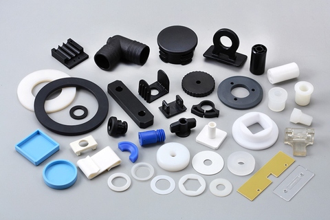
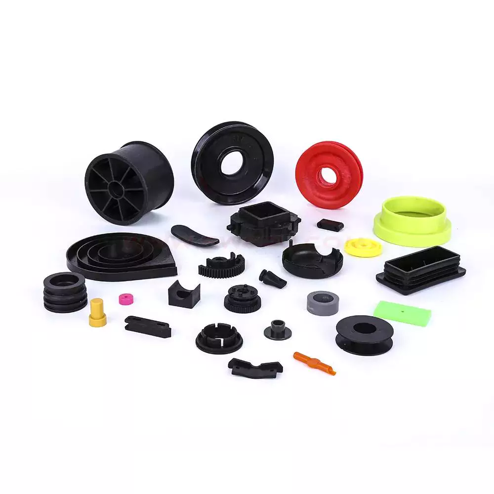
Detailed Photos
injection moulding
Company Profile
SENPO PRECISION Tooling Co., Ltd., Foreign Joint Ventures, was established in 2013. It is located at Building A2, No. 2082 CHINAMFG Rd., CHINAMFG Community, Shajing Blvd., Bao’an, Distr., HangZhou, ZheJiang , China. It focuses on the application and development of engineering plastics and focuses on high-quality engineering plastics precision parts and precision molds R&D, design and manufacturing, with a number of independent intellectual property rights.
The company’s products focus on passenger cars, commercial vehicles, new energy vehicles, high-end kitchen and bathroom appliances and other fields, providing customers with core components with high safety and important functionality. The product series includes automobile engine peripheral parts, automobile transmission system parts, automobile braking system parts, new energy vehicle parts, household water heater functional parts, household water purifier functional parts, precision industrial parts, etc.
In the context of “replacing steel with plastic”, the company aims to provide products with greater use value, is committed to the localization of high-end precision injection molded parts, and has established long-term and stable cooperative relationships with many internationally companies.
The company adheres to the concept of lean manufacturing and carefully manufactures every product.
DEVELOPING HangZhouSTONE
| *2014 Founded YAMANAMI, YAMANAMI was the original company name. *2015 *2016 *2017 *2018 |
*2019 Registered SENPO, specializes in global tooling & engineering services. *2571 *2571 *2571 *2571 |
Factory equipment list
Our Services
CNC Machining Services
Sheet Metal Fabrication
3D Printing Services
Plastic Injection Molding
3D ScHangZhou Services
3D Design Services
Silicone Rubber Mold Casting Services
Other Rapid Prototyping Services
Our Advantages
| Senpo Precision Tooling Co., Limited One-Stop Solution for Product Design and Manufacturing At Senpo Precision Tooling Co., Limited, we offer a comprehensive range of services to meet all your product design and manufacturing needs. Whether you require assistance with product design, prototyping, mold making, injection molding, or assembly, we have got you covered. Our team of professionals is dedicated to providing you with a seamless experience, saving you time and effort on communication. Wide Range of Materials: We specialize in working with plastic, silicone, metal, brass, and sheet metal, ensuring that we can cater to diverse project requirements. Professional Engineering Team: Our experienced engineering team closely tracks your project, ensuring that every detail is taken care of and delivering exceptional results. Competitive Pricing: With our extensive knowledge of different processes and intelligent process management, we are able to offer competitive prices without compromising on quality. Quality Warranty: Lifetime Sales-After Service: We provide lifetime sales-after service for all injection molds, ensuring that any issues or concerns are promptly addressed. 24-Hour Response: Our dedicated customer support team is available 24/7 to answer any questions or comments you may have. Mold Steel Lifetime Quality Warranty: Depending on the type of steel used, we offer warranties of up to 100,000 shots or 1,000,000 shots for our molds. CNC Machining and Prototype: All our products are meticulously CNC machined and prototype according to the provided drawings. We also conduct a 100% size check before shipment to ensure accuracy. Comprehensive Documentation: Our engineering team provides material certification, dimension reports, checklists for design, and detailed information about the mold shipment. Lifetime Sales-After Service: We provide lifetime sales-after service for all injection molds, ensuring that any issues or concerns are promptly addressed. 24-Hour Response: Our dedicated customer support team is available 24/7 to answer any questions or comments you may have. Mold Steel Lifetime Quality Warranty: Depending on the type of steel used, we offer warranties of up to 100,000 shots or 1,000,000 shots for our molds. CNC Machining and Prototype: All our products are meticulously CNC machined and prototype according to the provided drawings. We also conduct a 100% size check before shipment to ensure accuracy. Comprehensive Documentation: Our engineering team provides material certification, dimension reports, checklists for design, and detailed information about the mold shipment. |
Packaging & shipping
Delivery Time:
– RFQ: 24-48 hours
– Small quantity CNC machined components and prototypes: 3-5 days.
– Injection molds smaller than 450*450mm: 4 weeks.
– Injection molds smaller than 800*800mm: 5-6 weeks.
– Samples: 4-7 days CHINAMFG via DHL, FedEx, ***, etc.
Please note that these delivery times are applicable for Senpo Precision Tooling Co., Limited.
Our Services
| Product Engineerng Services | Mold Manufacturing Services | Product Manufacturing Services |
| 1.Plastic & metal product 3D design support,optimizing.
2.Plastic & metal product engineering DFM, solution. 3.Plastic & metal prototype manufacturing, testing. |
1.Plastic & die casting mold DFM, design, mold flow.
2.Plastic & die casting mold manufacturing. 3.Plastic & die casting mold injection molding. |
1.Plastic & metal part secondary process.
2.Plastic & metal part surface treatment. 3.Plastic & metal product assembly. |
FAQ
| Q1: Are you a trading company or manufacturer? A1: We are a manufacturer. Senpo Precision Tooling Co., Limited was established in 2013 with our own workshop and office. Q2: Where is your factory located? Q3: How is the quality control in your factory? Q4: If I provide you with a 3D drawing of my product, can you quote the price and make the mould accordingly? |
/* January 22, 2571 19:08:37 */!function(){function s(e,r){var a,o={};try{e&&e.split(“,”).forEach(function(e,t){e&&(a=e.match(/(.*?):(.*)$/))&&1
| Material: | PPS |
|---|---|
| Application: | Medical, Household, Electronics, Automotive, Agricultural |
| Certification: | TS16949, ISO |
| Product Feature: | Ultra-Precision Dimensions, Flame Retardant |
| Product Color: | Black, or Customized as Your Request |
| Machining Process: | Injection Molding |
| Samples: |
US$ 50/Piece
1 Piece(Min.Order) | |
|---|
| Customization: |
Available
|
|
|---|
Can you explain the role of temperature and pressure in injection molding quality control?
Temperature and pressure are two critical parameters in injection molding that significantly impact the quality control of the process. Let’s explore their roles in more detail:
Temperature:
The temperature in injection molding plays several important roles in ensuring quality control:
1. Material Flow and Fill:
The temperature of the molten plastic material affects its viscosity, or flowability. Higher temperatures reduce the material’s viscosity, allowing it to flow more easily into the mold cavities during the injection phase. Proper temperature control ensures optimal material flow and fill, preventing issues such as short shots, flow marks, or incomplete part filling. Temperature control also helps ensure consistent material properties and dimensional accuracy in the final parts.
2. Melting and Homogenization:
The temperature must be carefully controlled during the melting process to ensure complete melting and homogenization of the plastic material. Insufficient melting can result in unmelted particles or inconsistent material properties, leading to defects in the molded parts. Proper temperature control during the melting phase ensures uniform melting and mixing of additives, enhancing material homogeneity and the overall quality of the molded parts.
3. Cooling and Solidification:
After the molten plastic is injected into the mold, temperature control is crucial during the cooling and solidification phase. Proper cooling rates and uniform cooling help prevent issues such as warping, shrinkage, or part distortion. Controlling the temperature allows for consistent solidification throughout the part, ensuring dimensional stability and minimizing internal stresses. Temperature control also affects the part’s crystallinity and microstructure, which can impact its mechanical properties.
Pressure:
Pressure control is equally important in achieving quality control in injection molding:
1. Material Packing:
During the packing phase of injection molding, pressure is applied to the molten plastic material to compensate for shrinkage as it cools and solidifies. Proper pressure control ensures that the material is adequately packed into the mold cavities, minimizing voids, sinks, or part deformation. Insufficient packing pressure can lead to incomplete filling and poor part quality, while excessive pressure can cause excessive stress, part distortion, or flash.
2. Gate and Flow Control:
The pressure in injection molding influences the flow behavior of the material through the mold. The pressure at the gate, where the molten plastic enters the mold cavity, needs to be carefully controlled. The gate pressure affects the material’s flow rate, filling pattern, and packing efficiency. Optimal gate pressure ensures uniform flow and fill, preventing issues like flow lines, weld lines, or air traps that can compromise part quality.
3. Ejection and Part Release:
Pressure control is essential during the ejection phase to facilitate the easy removal of the molded part from the mold. Adequate ejection pressure helps overcome any adhesion or friction between the part and the mold surfaces, ensuring smooth and damage-free part release. Improper ejection pressure can result in part sticking, part deformation, or mold damage.
4. Process Monitoring and Feedback:
Monitoring and controlling the temperature and pressure parameters in real-time are crucial for quality control. Advanced injection molding machines are equipped with sensors and control systems that continuously monitor temperature and pressure. These systems provide feedback and allow for adjustments during the process to maintain optimum conditions and ensure consistent part quality.
Overall, temperature and pressure control in injection molding are vital for achieving quality control. Proper temperature control ensures optimal material flow, melting, homogenization, cooling, and solidification, while pressure control ensures proper material packing, gate and flow control, ejection, and part release. Monitoring and controlling these parameters throughout the injection molding process contribute to the production of high-quality parts with consistent dimensions, mechanical properties, and surface finish.
How do injection molded parts enhance the overall efficiency and functionality of products and equipment?
Injection molded parts play a crucial role in enhancing the overall efficiency and functionality of products and equipment. They offer numerous advantages that make them a preferred choice in various industries. Here’s a detailed explanation of how injection molded parts contribute to improved efficiency and functionality:
1. Design Flexibility:
Injection molding allows for intricate and complex part designs that can be customized to meet specific requirements. The flexibility in design enables the integration of multiple features, such as undercuts, threads, hinges, and snap fits, into a single molded part. This versatility enhances the functionality of the product or equipment by enabling the creation of parts that are precisely tailored to their intended purpose.
2. High Precision and Reproducibility:
Injection molding offers excellent dimensional accuracy and repeatability, ensuring consistent part quality throughout production. The use of precision molds and advanced molding techniques allows for the production of parts with tight tolerances and intricate geometries. This high precision and reproducibility enhance the efficiency of products and equipment by ensuring proper fit, alignment, and functionality of the molded parts.
3. Cost-Effective Mass Production:
Injection molding is a highly efficient and cost-effective method for mass production. Once the molds are created, the injection molding process can rapidly produce a large number of identical parts in a short cycle time. The ability to produce parts in high volumes streamlines the manufacturing process, reduces labor costs, and ensures consistent part quality. This cost-effectiveness contributes to overall efficiency and enables the production of affordable products and equipment.
4. Material Selection:
Injection molding offers a wide range of material options, including engineering thermoplastics, elastomers, and even certain metal alloys. The ability to choose from various materials with different properties allows manufacturers to select the most suitable material for each specific application. The right material selection enhances the functionality of the product or equipment by providing the desired mechanical, thermal, and chemical properties required for optimal performance.
5. Structural Integrity and Durability:
Injection molded parts are known for their excellent structural integrity and durability. The molding process ensures uniform material distribution, resulting in parts with consistent strength and reliability. The elimination of weak points, such as seams or joints, enhances the overall structural integrity of the product or equipment. Additionally, injection molded parts are resistant to impact, wear, and environmental factors, ensuring long-lasting functionality in demanding applications.
6. Integration of Features:
Injection molding enables the integration of multiple features into a single part. This eliminates the need for assembly or additional components, simplifying the manufacturing process and reducing production time and costs. The integration of features such as hinges, fasteners, or mounting points enhances the overall efficiency and functionality of the product or equipment by providing convenient and streamlined solutions.
7. Lightweight Design:
Injection molded parts can be manufactured with lightweight materials without compromising strength or durability. This is particularly advantageous in industries where weight reduction is critical, such as automotive, aerospace, and consumer electronics. The use of lightweight injection molded parts improves energy efficiency, reduces material costs, and enhances the overall performance and efficiency of the products and equipment.
8. Consistent Surface Finish:
Injection molding produces parts with a consistent and high-quality surface finish. The use of polished or textured molds ensures that the molded parts have smooth, aesthetic surfaces without the need for additional finishing operations. This consistent surface finish enhances the overall functionality and visual appeal of the product or equipment, contributing to a positive user experience.
9. Customization and Branding:
Injection molding allows for customization and branding options, such as incorporating logos, labels, or surface textures, directly into the molded parts. This customization enhances the functionality and marketability of products and equipment by providing a unique identity and reinforcing brand recognition.
Overall, injection molded parts offer numerous advantages that enhance the efficiency and functionality of products and equipment. Their design flexibility, precision, cost-effectiveness, material selection, structural integrity, lightweight design, and customization capabilities make them a preferred choice for a wide range of applications across industries.
Are there different types of injection molded parts, such as automotive components or medical devices?
Yes, there are various types of injection molded parts that are specifically designed for different industries and applications. Injection molding is a versatile manufacturing process capable of producing complex and precise parts with high efficiency and repeatability. Here are some examples of different types of injection molded parts:
1. Automotive Components:
Injection molding plays a critical role in the automotive industry, where it is used to manufacture a wide range of components. Some common injection molded automotive parts include:
- Interior components: Dashboard panels, door handles, trim pieces, instrument clusters, and center consoles.
- Exterior components: Bumpers, grilles, body panels, mirror housings, and wheel covers.
- Under-the-hood components: Engine covers, air intake manifolds, cooling system parts, and battery housings.
- Electrical components: Connectors, switches, sensor housings, and wiring harnesses.
- Seating components: Seat frames, headrests, armrests, and seatbelt components.
2. Medical Devices:
The medical industry relies on injection molding for the production of a wide range of medical devices and components. These parts often require high precision, biocompatibility, and sterilizability. Examples of injection molded medical devices include:
- Syringes and injection pens
- Implantable devices: Catheters, pacemaker components, orthopedic implants, and surgical instruments.
- Diagnostic equipment: Test tubes, specimen containers, and laboratory consumables.
- Disposable medical products: IV components, respiratory masks, blood collection tubes, and wound care products.
3. Consumer Products:
Injection molding is widely used in the production of consumer products due to its ability to mass-produce parts with high efficiency. Examples of injection molded consumer products include:
- Household appliances: Television and audio equipment components, refrigerator parts, and vacuum cleaner components.
- Electronics: Mobile phone cases, computer keyboard and mouse, camera components, and power adapters.
- Toys and games: Action figures, building blocks, puzzles, and board game components.
- Personal care products: Toothbrushes, razor handles, cosmetic containers, and hairdryer components.
- Home improvement products: Light switch covers, door handles, power tool housings, and storage containers.
4. Packaging:
Injection molding is widely used in the packaging industry to produce a wide variety of plastic containers, caps, closures, and packaging components. Some examples include:
- Bottles and containers for food, beverages, personal care products, and household chemicals.
- Caps and closures for bottles and jars.
- Thin-walled packaging for food products such as trays, cups, and lids.
- Blister packs and clamshell packaging for retail products.
- Packaging inserts and protective foam components.
5. Electronics and Electrical Components:
Injection molding is widely used in the electronics industry for the production of various components and enclosures. Examples include:
- Connectors and housings for electrical and electronic devices.
- Switches, buttons, and control panels.
- PCB (Printed Circuit Board) components and enclosures.
- LED (Light-Emitting Diode) components and light fixtures.
- Power adapters and chargers.
These are just a few examples of the different types of injection molded parts. The versatility of injection molding allows for the production of parts in various industries, ranging from automotive and medical to consumer products, packaging, electronics, and more. The specific design requirements and performance characteristics of each part determine the choice of materials, tooling, and manufacturing processes for injection molding.


editor by Dream 2024-04-26
China Professional OEM/ODM Precision Machinery Household Autoplastic Injection Molded Customized/CNC Machining/Mould Parts with PP, PE, PVC, ABS, PA6
Product Description
Company Intrudcution:
__________________________________________________________________________________________________________________
China Exact Plastic is a leading manufacturer of Molded Plastic Injection Parts, focus on producing injection molding plastic products, CHINAMFG and Tooling, we are supplying different kinds of products used for various industrials from Machinery, Automotive to Household all over the world.
We have rich experiences to cooperate with manufacturers, wholesaler, trading companies and agents in North America, European countries, such as USA, Canada, Germany, France, Italy, Spain, Netherland etc. So we have confidence to suit different customers and various requirements.
We have professional engineering & sale team engineers who is good at product design & develop, plastic injection mold design, we can offer One-Stop service for Mold and Plastic Product, from drawing design, tooling and samples, mass productions, package and transportation. Our team is thoughtful and good at understanding your idea and points, where help to make your work much easy. 24*7 communication service, whenever you need us, we are here for you.
In all, let us to be your reliable OEM partner!
Product Description:
__________________________________________________________________________________________________________________
Material:PP,PE,ABS,PA,PVC,PS,PC…
Color:Any color available
Package:Polybag, export Carton, Pallets
Sample Time:7-20days
Logo:Custoized with Ai Printed Embossed
Design:SolidWorks, UG, ProE, SLA, Auto CAD
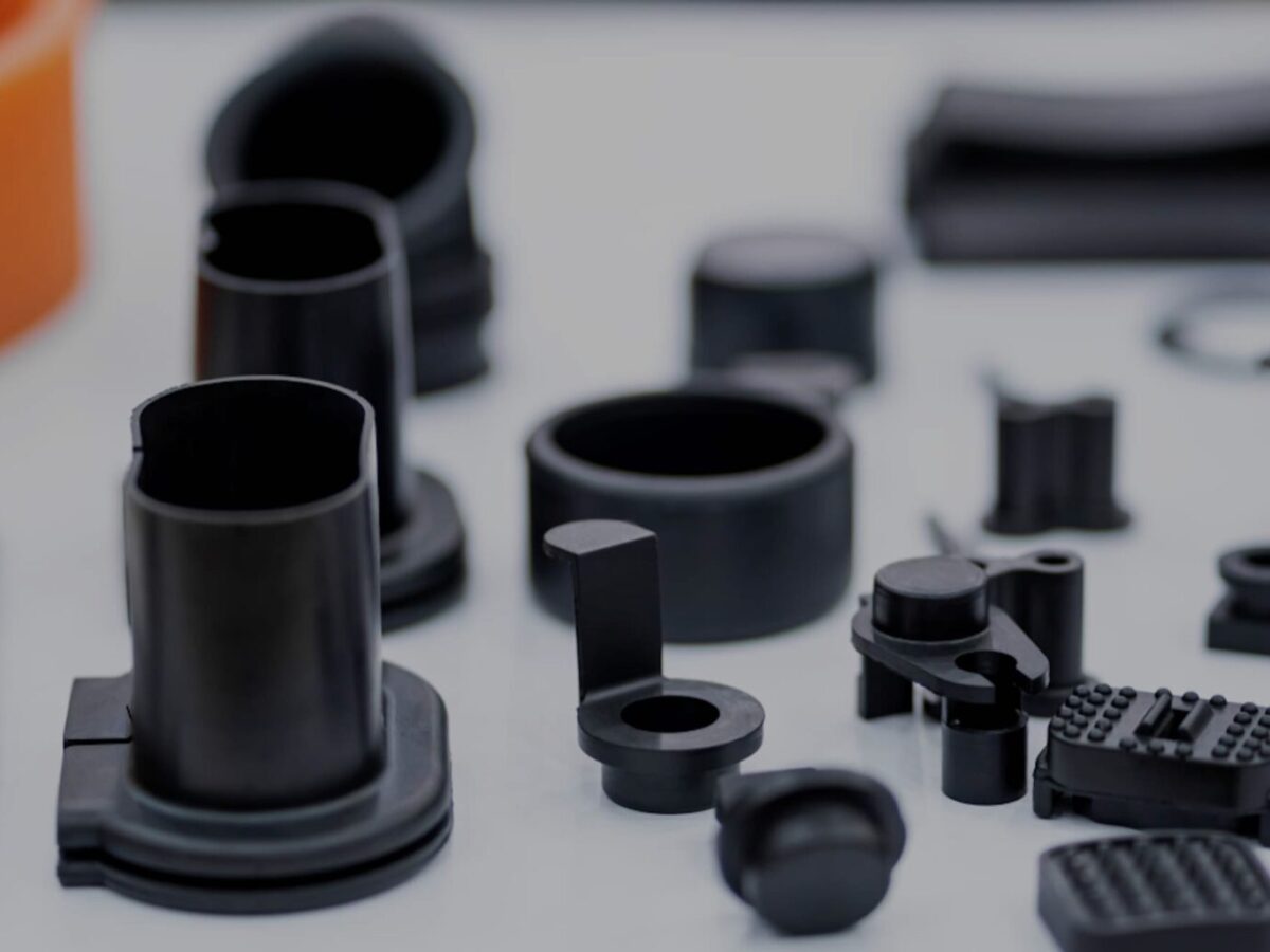
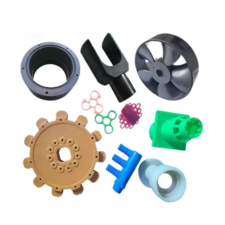
Product View:
__________________________________________________________________________________________________________________
Workshop Display:
__________________________________________________________________________________________________________________
Capability
- OEM/ODM product manufactory
- Mould and Product one-stop service
- Prototype, Sampling and Mass production
- Develop&Design, professional engineering team, fast communication to covert idea to real product
- Flexible choose of material, dimensions control and surface finish
- Assembly product is available.
- Various Auxiliary process such as overmolding, assembling, bonding, printing, sonic welding, cnc-machining
RFQ
- What is the lead time? —40days
- Are you a trading company or manufacturer?—Yes. We are a factory with our own mold plant.
- Life time of the mould.—Our mould life is very long, can produce at least 500,000times.
- Product quality?—Our quality is good, we manufacture and export customized plastic products to USA, Canada and Europe.
- Can you produce mould or only parts?—We have our own mould plant, we can do CHINAMFG and mould together.
- What’s moq?—Usually our moq is 1000pcs.
- We have an idea, can you help to create the product?—Yes, we have professional communication engineering team to talk with you to form the product easily, quickly and functionally.
| Material: | PP |
|---|---|
| Application: | Medical, Household, Electronics, Automotive, Agricultural, Garden, Construction, Machinery |
| Certification: | RoHS, ISO |
| Size: | Customized |
| Colour: | Any Color Is Available. |
| Transport Package: | Polybag, Carton, Pallet |
| Samples: |
US$ 100/Piece
1 Piece(Min.Order) | |
|---|
| Customization: |
Available
|
|
|---|
What factors influence the design and tooling of injection molded parts for specific applications?
Several factors play a crucial role in influencing the design and tooling of injection molded parts for specific applications. The following are key factors that need to be considered:
1. Functionality and Performance Requirements:
The intended functionality and performance requirements of the part heavily influence its design and tooling. Factors such as strength, durability, dimensional accuracy, chemical resistance, and temperature resistance are essential considerations. The part’s design must be optimized to meet these requirements while ensuring proper functionality and performance in its intended application.
2. Material Selection:
The choice of material for injection molding depends on the specific application and its requirements. Different materials have varying properties, such as strength, flexibility, heat resistance, chemical resistance, and electrical conductivity. The material selection influences the design and tooling considerations, as the part’s geometry and structure must be compatible with the selected material’s properties.
3. Part Complexity and Geometry:
The complexity and geometry of the part significantly impact its design and tooling. Complex parts with intricate features, undercuts, thin walls, or varying thicknesses may require specialized tooling and mold designs. The part’s geometry must be carefully considered to ensure proper mold filling, cooling, ejection, and dimensional stability during the injection molding process.
4. Manufacturing Cost and Efficiency:
The design and tooling of injection molded parts are also influenced by manufacturing cost and efficiency considerations. Design features that reduce material usage, minimize cycle time, and optimize the use of the injection molding machine can help lower production costs. Efficient tooling designs, such as multi-cavity molds or family molds, can increase productivity and reduce per-part costs.
5. Moldability and Mold Design:
The moldability of the part, including factors like draft angles, wall thickness, and gate location, affects the mold design. The part should be designed to facilitate proper flow of molten plastic during injection, ensure uniform cooling, and allow for easy part ejection. The tooling design, such as the number of cavities, gate design, and cooling system, is influenced by the part’s moldability requirements.
6. Regulatory and Industry Standards:
Specific applications, especially in industries like automotive, aerospace, and medical, may have regulatory and industry standards that influence the design and tooling considerations. Compliance with these standards regarding materials, dimensions, safety, and performance requirements is essential and may impact the design choices and tooling specifications.
7. Assembly and Integration:
If the injection molded part needs to be assembled or integrated with other components or systems, the design and tooling must consider the assembly process and requirements. Features such as snap fits, interlocking mechanisms, or specific mating surfacescan be incorporated into the part’s design to facilitate efficient assembly and integration.
8. Aesthetics and Branding:
In consumer products and certain industries, the aesthetic appearance and branding of the part may be crucial. Design considerations such as surface finish, texture, color, and the inclusion of logos or branding elements may be important factors that influence the design and tooling decisions.
Overall, the design and tooling of injection molded parts for specific applications are influenced by a combination of functional requirements, material considerations, part complexity, manufacturing cost and efficiency, moldability, regulatory standards, assembly requirements, and aesthetic factors. It is essential to carefully consider these factors to achieve optimal part design and successful injection molding production.
How do injection molded parts enhance the overall efficiency and functionality of products and equipment?
Injection molded parts play a crucial role in enhancing the overall efficiency and functionality of products and equipment. They offer numerous advantages that make them a preferred choice in various industries. Here’s a detailed explanation of how injection molded parts contribute to improved efficiency and functionality:
1. Design Flexibility:
Injection molding allows for intricate and complex part designs that can be customized to meet specific requirements. The flexibility in design enables the integration of multiple features, such as undercuts, threads, hinges, and snap fits, into a single molded part. This versatility enhances the functionality of the product or equipment by enabling the creation of parts that are precisely tailored to their intended purpose.
2. High Precision and Reproducibility:
Injection molding offers excellent dimensional accuracy and repeatability, ensuring consistent part quality throughout production. The use of precision molds and advanced molding techniques allows for the production of parts with tight tolerances and intricate geometries. This high precision and reproducibility enhance the efficiency of products and equipment by ensuring proper fit, alignment, and functionality of the molded parts.
3. Cost-Effective Mass Production:
Injection molding is a highly efficient and cost-effective method for mass production. Once the molds are created, the injection molding process can rapidly produce a large number of identical parts in a short cycle time. The ability to produce parts in high volumes streamlines the manufacturing process, reduces labor costs, and ensures consistent part quality. This cost-effectiveness contributes to overall efficiency and enables the production of affordable products and equipment.
4. Material Selection:
Injection molding offers a wide range of material options, including engineering thermoplastics, elastomers, and even certain metal alloys. The ability to choose from various materials with different properties allows manufacturers to select the most suitable material for each specific application. The right material selection enhances the functionality of the product or equipment by providing the desired mechanical, thermal, and chemical properties required for optimal performance.
5. Structural Integrity and Durability:
Injection molded parts are known for their excellent structural integrity and durability. The molding process ensures uniform material distribution, resulting in parts with consistent strength and reliability. The elimination of weak points, such as seams or joints, enhances the overall structural integrity of the product or equipment. Additionally, injection molded parts are resistant to impact, wear, and environmental factors, ensuring long-lasting functionality in demanding applications.
6. Integration of Features:
Injection molding enables the integration of multiple features into a single part. This eliminates the need for assembly or additional components, simplifying the manufacturing process and reducing production time and costs. The integration of features such as hinges, fasteners, or mounting points enhances the overall efficiency and functionality of the product or equipment by providing convenient and streamlined solutions.
7. Lightweight Design:
Injection molded parts can be manufactured with lightweight materials without compromising strength or durability. This is particularly advantageous in industries where weight reduction is critical, such as automotive, aerospace, and consumer electronics. The use of lightweight injection molded parts improves energy efficiency, reduces material costs, and enhances the overall performance and efficiency of the products and equipment.
8. Consistent Surface Finish:
Injection molding produces parts with a consistent and high-quality surface finish. The use of polished or textured molds ensures that the molded parts have smooth, aesthetic surfaces without the need for additional finishing operations. This consistent surface finish enhances the overall functionality and visual appeal of the product or equipment, contributing to a positive user experience.
9. Customization and Branding:
Injection molding allows for customization and branding options, such as incorporating logos, labels, or surface textures, directly into the molded parts. This customization enhances the functionality and marketability of products and equipment by providing a unique identity and reinforcing brand recognition.
Overall, injection molded parts offer numerous advantages that enhance the efficiency and functionality of products and equipment. Their design flexibility, precision, cost-effectiveness, material selection, structural integrity, lightweight design, and customization capabilities make them a preferred choice for a wide range of applications across industries.
What are injection molded parts, and how are they manufactured?
Injection molded parts are components or products that are produced through the injection molding manufacturing process. Injection molding is a widely used manufacturing technique for creating plastic parts with high precision, complexity, and efficiency. Here’s a detailed explanation of injection molded parts and the process of manufacturing them:
Injection Molding Process:
The injection molding process involves the following steps:
1. Mold Design:
The first step in manufacturing injection molded parts is designing the mold. The mold is a custom-made tool that defines the shape and features of the final part. It is typically made from steel or aluminum and consists of two halves: the cavity and the core. The mold design takes into account factors such as part geometry, material selection, cooling requirements, and ejection mechanism.
2. Material Selection:
The next step is selecting the appropriate material for the injection molding process. Thermoplastic polymers are commonly used due to their ability to melt and solidify repeatedly without significant degradation. The material choice depends on the desired properties of the final part, such as strength, flexibility, transparency, or chemical resistance.
3. Melting and Injection:
In the injection molding machine, the selected thermoplastic material is melted and brought to a molten state. The molten material, called the melt, is then injected into the mold under high pressure. The injection is performed through a nozzle and a runner system that delivers the molten material to the mold cavity.
4. Cooling:
After the molten material is injected into the mold, it begins to cool and solidify. Cooling is a critical phase of the injection molding process as it determines the final part’s dimensional accuracy, strength, and other properties. The mold is designed with cooling channels or inserts to facilitate the efficient and uniform cooling of the part. Cooling time can vary depending on factors such as part thickness, material properties, and mold design.
5. Mold Opening and Ejection:
Once the injected material has sufficiently cooled and solidified, the mold opens, separating the two halves. Ejector pins or other mechanisms are used to push or release the part from the mold cavity. The ejection system must be carefully designed to avoid damaging the part during the ejection process.
6. Finishing:
After ejection, the injection molded part may undergo additional finishing processes, such as trimming excess material, removing sprues or runners, and applying surface treatments or textures. These processes help achieve the desired final appearance and functionality of the part.
Advantages of Injection Molded Parts:
Injection molded parts offer several advantages:
1. High Precision and Complexity:
Injection molding allows for the creation of parts with high precision and intricate details. The molds can produce complex shapes, fine features, and precise dimensions, enabling the manufacturing of parts with tight tolerances.
2. Cost-Effective Mass Production:
Injection molding is a highly efficient process suitable for large-scale production. Once the mold is created, the manufacturing process can be automated, resulting in fast and cost-effective production of identical parts. The high production volumes help reduce per-unit costs.
3. Material Versatility:
Injection molding supports a wide range of thermoplastic materials, allowing for versatility in material selection based on the desired characteristics of the final part. Different materials can be used to achieve specific properties such as strength, flexibility, heat resistance, or chemical resistance.
4. Strength and Durability:
Injection molded parts can exhibit excellent strength and durability. The molding process ensures that the material is uniformly distributed, resulting in consistent mechanical properties throughout the part. This makes injection molded parts suitable for various applications that require structural integrity and longevity.
5. Minimal Post-Processing:
Injection molded parts often require minimal post-processing. The high precision and quality achieved during the molding process reduce the need for extensive additional machining or finishing operations, saving time and costs.
6. Design Flexibility:
With injection molding, designers have significant flexibility in part design. The process can accommodate complex geometries, undercuts, thin walls, and other design features that may be challenging or costly with other manufacturing methods. This flexibility allows for innovation and optimization of part functionality.
In summary, injection molded parts are components or products manufactured through the injection molding process. This process involves designing amold, selecting the appropriate material, melting and injecting the material into the mold, cooling and solidifying the part, opening the mold and ejecting the part, and applying finishing processes as necessary. Injection molded parts offer advantages such as high precision, complexity, cost-effective mass production, material versatility, strength and durability, minimal post-processing, and design flexibility. These factors contribute to the widespread use of injection molding in various industries for producing high-quality plastic parts.
editor by CX 2023-12-12
China Hot selling Custom OEM Injection Molded Plastic Rubber Machinery Parts
Product Description
[Custom oem injection molded plastic rubber machinery parts]
Company Information
Our company is located in HangZhou City,ZheJiang , the world’s manufacturing capital. We are dedicated to the production of CNC milling & turning parts and high-precision mold components, machined parts and all kinds of Knives & Blades according to the requirements of customers from different industries. Products are mainly exported to Europe, USA and Japan, and obtains favor reputation from customers.
We will always adhere to the values of “Details, Focusing, Principal, Leading” and the business philosophy of “Constantly Improvement, Precision Dedication” to serve the customers more and better and to create value for customers.
OUR SERVICES
We specialize in CNC Machined Parts,Precision Injection Mold Parts, Plasic Injection Moulding, and Machining all kinds of Knives and Blades.
OUR INDUSTRIES
We serve in the industries of Automobile, Mobile Phone, Computer and Medical Parts, Home Appliances, Led Lights, Electrotechnical Application, Aerospace, Consumer Electronics, Watches, Agriculture, Food Packaging & Processing and Archery, Telescope,UAV,Robot,etc.
Products Description
| Material: | PMMA,PC,PP,PEEK,PU,PA,POM,PE,UPE,etc. |
| Color: | White,black,green,nature,blue,yellow,etc. |
| Diameter: | 5-1000mm,or customized. |
| Shape: | According to your drawings. |
| Certification: | ISO9001,SGS,Test Report,RoSH. |
| Advantage | One stop procurement. |
| Packing | Plastic bags,Cartons,Wodden case,Pallet,Container,ect. |
| Mold Processing | CNC machining,Drilling, EDM,and then testing. |
| File Formats | Solid Works(STEP), Pro/Engineer, AutoCAD(DXF,DWG), PDF,etc. |
| Negotiations: | Quality,material,price,payment,delivery time item and so on |
| R&D: | According to customer’s requirements,we could design and improve the 3D moulding files. |
| We will send our customers the 3D files for confirmation.Once the customers approved,then we will start to build the mold. | |
| Sample confirm: | We can send the trial sample to customers for approval, If the customers are not satisfied it, then we will modify the mould. |
| Other | 24 hours instant and comfortable customer service. |
| Shipping status notification during delivery. | |
| Regular notification of new styles & hot selling styles. |
Logistic
| Shaping Mode: | Injection Mould |
|---|---|
| Surface Finish Process: | Polishing |
| Mould Cavity: | Multi Cavity |
| Plastic Material: | ABS |
| Application: | Car, Household Appliances, Furniture, Commodity, Electronic, Home Use |
| Design Software: | Pro-E |
| Samples: |
US$ 1/Piece
1 Piece(Min.Order) | |
|---|
| Customization: |
Available
|
|
|---|
What factors influence the design and tooling of injection molded parts for specific applications?
Several factors play a crucial role in influencing the design and tooling of injection molded parts for specific applications. The following are key factors that need to be considered:
1. Functionality and Performance Requirements:
The intended functionality and performance requirements of the part heavily influence its design and tooling. Factors such as strength, durability, dimensional accuracy, chemical resistance, and temperature resistance are essential considerations. The part’s design must be optimized to meet these requirements while ensuring proper functionality and performance in its intended application.
2. Material Selection:
The choice of material for injection molding depends on the specific application and its requirements. Different materials have varying properties, such as strength, flexibility, heat resistance, chemical resistance, and electrical conductivity. The material selection influences the design and tooling considerations, as the part’s geometry and structure must be compatible with the selected material’s properties.
3. Part Complexity and Geometry:
The complexity and geometry of the part significantly impact its design and tooling. Complex parts with intricate features, undercuts, thin walls, or varying thicknesses may require specialized tooling and mold designs. The part’s geometry must be carefully considered to ensure proper mold filling, cooling, ejection, and dimensional stability during the injection molding process.
4. Manufacturing Cost and Efficiency:
The design and tooling of injection molded parts are also influenced by manufacturing cost and efficiency considerations. Design features that reduce material usage, minimize cycle time, and optimize the use of the injection molding machine can help lower production costs. Efficient tooling designs, such as multi-cavity molds or family molds, can increase productivity and reduce per-part costs.
5. Moldability and Mold Design:
The moldability of the part, including factors like draft angles, wall thickness, and gate location, affects the mold design. The part should be designed to facilitate proper flow of molten plastic during injection, ensure uniform cooling, and allow for easy part ejection. The tooling design, such as the number of cavities, gate design, and cooling system, is influenced by the part’s moldability requirements.
6. Regulatory and Industry Standards:
Specific applications, especially in industries like automotive, aerospace, and medical, may have regulatory and industry standards that influence the design and tooling considerations. Compliance with these standards regarding materials, dimensions, safety, and performance requirements is essential and may impact the design choices and tooling specifications.
7. Assembly and Integration:
If the injection molded part needs to be assembled or integrated with other components or systems, the design and tooling must consider the assembly process and requirements. Features such as snap fits, interlocking mechanisms, or specific mating surfacescan be incorporated into the part’s design to facilitate efficient assembly and integration.
8. Aesthetics and Branding:
In consumer products and certain industries, the aesthetic appearance and branding of the part may be crucial. Design considerations such as surface finish, texture, color, and the inclusion of logos or branding elements may be important factors that influence the design and tooling decisions.
Overall, the design and tooling of injection molded parts for specific applications are influenced by a combination of functional requirements, material considerations, part complexity, manufacturing cost and efficiency, moldability, regulatory standards, assembly requirements, and aesthetic factors. It is essential to carefully consider these factors to achieve optimal part design and successful injection molding production.
How do innovations and advancements in injection molding technology influence part design and production?
Innovations and advancements in injection molding technology have a significant influence on part design and production. These advancements introduce new capabilities, enhance process efficiency, improve part quality, and expand the range of applications for injection molded parts. Here’s a detailed explanation of how innovations and advancements in injection molding technology influence part design and production:
Design Freedom:
Advancements in injection molding technology have expanded the design freedom for part designers. With the introduction of advanced software tools, such as computer-aided design (CAD) and simulation software, designers can create complex geometries, intricate features, and highly optimized designs. The use of 3D modeling and simulation allows for the identification and resolution of potential design issues before manufacturing. This design freedom enables the production of innovative and highly functional parts that were previously challenging or impossible to manufacture using conventional techniques.
Improved Precision and Accuracy:
Innovations in injection molding technology have led to improved precision and accuracy in part production. High-precision molds, advanced control systems, and closed-loop feedback mechanisms ensure precise control over the molding process variables, such as temperature, pressure, and cooling. This level of control results in parts with tight tolerances, consistent dimensions, and improved surface finishes. Enhanced precision and accuracy enable the production of parts that meet strict quality requirements, fit seamlessly with other components, and perform reliably in their intended applications.
Material Advancements:
The development of new materials and material combinations specifically formulated for injection molding has expanded the range of properties available to part designers. Innovations in materials include high-performance engineering thermoplastics, bio-based polymers, reinforced composites, and specialty materials with unique properties. These advancements allow for the production of parts with enhanced mechanical strength, improved chemical resistance, superior heat resistance, and customized performance characteristics. Material advancements in injection molding technology enable the creation of parts that can withstand demanding operating conditions and meet the specific requirements of various industries.
Process Efficiency:
Innovations in injection molding technology have introduced process optimizations that improve efficiency and productivity. Advanced automation, robotics, and real-time monitoring systems enable faster cycle times, reduced scrap rates, and increased production throughput. Additionally, innovations like multi-cavity molds, hot-runner systems, and micro-injection molding techniques improve material utilization and reduce production costs. Increased process efficiency allows for the economical production of high-quality parts in larger quantities, meeting the demands of industries that require high-volume production.
Overmolding and Multi-Material Molding:
Advancements in injection molding technology have enabled the integration of multiple materials or components into a single part through overmolding or multi-material molding processes. Overmolding allows for the encapsulation of inserts, such as metal components or electronics, with a thermoplastic material in a single molding cycle. This enables the creation of parts with improved functionality, enhanced aesthetics, and simplified assembly. Multi-material molding techniques, such as co-injection molding or sequential injection molding, enable the production of parts with multiple colors, varying material properties, or complex material combinations. These capabilities expand the design possibilities and allow for the creation of innovative parts with unique features and performance characteristics.
Additive Manufacturing Integration:
The integration of additive manufacturing, commonly known as 3D printing, with injection molding technology has opened up new possibilities for part design and production. Additive manufacturing can be used to create complex mold geometries, conformal cooling channels, or custom inserts, which enhance part quality, reduce cycle times, and improve part performance. By combining additive manufacturing and injection molding, designers can explore new design concepts, produce rapid prototypes, and efficiently manufacture customized or low-volume production runs.
Sustainability and Eco-Friendly Solutions:
Advancements in injection molding technology have also focused on sustainability and eco-friendly solutions. This includes the development of biodegradable and compostable materials, recycling technologies for post-consumer and post-industrial waste, and energy-efficient molding processes. These advancements enable the production of environmentally friendly parts that contribute to reducing the carbon footprint and meeting sustainability goals.
Overall, innovations and advancements in injection molding technology have revolutionized part design and production. They have expanded design possibilities, improved precision and accuracy, introduced new materials, enhanced process efficiency, enabled overmolding and multi-material molding, integrated additive manufacturing, and promoted sustainability. These advancements empower part designers and manufacturers to create highly functional, complex, and customized parts that meet the demands of various industries and contribute to overall process efficiency and sustainability.
What are injection molded parts, and how are they manufactured?
Injection molded parts are components or products that are produced through the injection molding manufacturing process. Injection molding is a widely used manufacturing technique for creating plastic parts with high precision, complexity, and efficiency. Here’s a detailed explanation of injection molded parts and the process of manufacturing them:
Injection Molding Process:
The injection molding process involves the following steps:
1. Mold Design:
The first step in manufacturing injection molded parts is designing the mold. The mold is a custom-made tool that defines the shape and features of the final part. It is typically made from steel or aluminum and consists of two halves: the cavity and the core. The mold design takes into account factors such as part geometry, material selection, cooling requirements, and ejection mechanism.
2. Material Selection:
The next step is selecting the appropriate material for the injection molding process. Thermoplastic polymers are commonly used due to their ability to melt and solidify repeatedly without significant degradation. The material choice depends on the desired properties of the final part, such as strength, flexibility, transparency, or chemical resistance.
3. Melting and Injection:
In the injection molding machine, the selected thermoplastic material is melted and brought to a molten state. The molten material, called the melt, is then injected into the mold under high pressure. The injection is performed through a nozzle and a runner system that delivers the molten material to the mold cavity.
4. Cooling:
After the molten material is injected into the mold, it begins to cool and solidify. Cooling is a critical phase of the injection molding process as it determines the final part’s dimensional accuracy, strength, and other properties. The mold is designed with cooling channels or inserts to facilitate the efficient and uniform cooling of the part. Cooling time can vary depending on factors such as part thickness, material properties, and mold design.
5. Mold Opening and Ejection:
Once the injected material has sufficiently cooled and solidified, the mold opens, separating the two halves. Ejector pins or other mechanisms are used to push or release the part from the mold cavity. The ejection system must be carefully designed to avoid damaging the part during the ejection process.
6. Finishing:
After ejection, the injection molded part may undergo additional finishing processes, such as trimming excess material, removing sprues or runners, and applying surface treatments or textures. These processes help achieve the desired final appearance and functionality of the part.
Advantages of Injection Molded Parts:
Injection molded parts offer several advantages:
1. High Precision and Complexity:
Injection molding allows for the creation of parts with high precision and intricate details. The molds can produce complex shapes, fine features, and precise dimensions, enabling the manufacturing of parts with tight tolerances.
2. Cost-Effective Mass Production:
Injection molding is a highly efficient process suitable for large-scale production. Once the mold is created, the manufacturing process can be automated, resulting in fast and cost-effective production of identical parts. The high production volumes help reduce per-unit costs.
3. Material Versatility:
Injection molding supports a wide range of thermoplastic materials, allowing for versatility in material selection based on the desired characteristics of the final part. Different materials can be used to achieve specific properties such as strength, flexibility, heat resistance, or chemical resistance.
4. Strength and Durability:
Injection molded parts can exhibit excellent strength and durability. The molding process ensures that the material is uniformly distributed, resulting in consistent mechanical properties throughout the part. This makes injection molded parts suitable for various applications that require structural integrity and longevity.
5. Minimal Post-Processing:
Injection molded parts often require minimal post-processing. The high precision and quality achieved during the molding process reduce the need for extensive additional machining or finishing operations, saving time and costs.
6. Design Flexibility:
With injection molding, designers have significant flexibility in part design. The process can accommodate complex geometries, undercuts, thin walls, and other design features that may be challenging or costly with other manufacturing methods. This flexibility allows for innovation and optimization of part functionality.
In summary, injection molded parts are components or products manufactured through the injection molding process. This process involves designing amold, selecting the appropriate material, melting and injecting the material into the mold, cooling and solidifying the part, opening the mold and ejecting the part, and applying finishing processes as necessary. Injection molded parts offer advantages such as high precision, complexity, cost-effective mass production, material versatility, strength and durability, minimal post-processing, and design flexibility. These factors contribute to the widespread use of injection molding in various industries for producing high-quality plastic parts.
editor by CX 2023-11-23
China Custom Custom OEM CZPT Parts for Machinery and Heavy Equipment injection mould parts and functions
Product Description
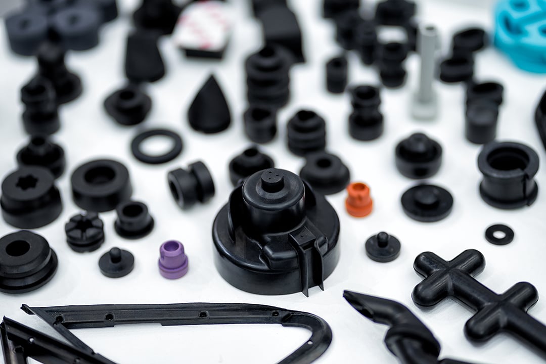
CZPT partsa are made by molding tooling with all kinds of material, are widely used for lots of area,such as machinery,construction,building etc
Production Description
| Item Name | Molded rubber part |
| Material | Silicone, EPDM, PVC, TPE, ,Neoprene, etc |
| Color | Black, white or as client’s requirement |
| Hardness | 30~90ShA |
| Dimension | As client’s requirement |
| Temperature range | ~50 to 380ºC |
| Function | Sealing ,waterproof,dust proof, anti-slip, vibration resistant |
| Application | Medical industry, machinery industry, automotive industry, etc |
| Process | Molding or Injection |
| Certification | SGS, ROHS, REACH, FDA, etc |
| OEM | Welcome to customized |
Plastic Injection Mould making
1.Samples/Drawing &Requirement from you
2.Mould design:we will Communicate and Exchange the opinion with you after you place order.
3.Material Purchase:Steel cutting and Mould base tooling.
4.Assembling.
5.Inspection of mould : following and controlling the tooling processing.
6.Mould testing:We will inform you the date.Than will send the sample’s inspection report&injection parameters with the sample to you!
7.Your instruction &confirmation for shipment.
8.Ready made mould before packing.
9.We provide any differeny kinds of plastic injection mould, blow mould, silicone mould, die casting mould service.
Plastic molding Specification
1. Professional manufacturer,design,production injection mould and stamping mould quality control
2. rich export experience plastic injection mould and stamping mould
3. Reasonable price of design mould
4. Cavities: single or as per your requirements cavity
5. Treatment: S45C Pretreat>25Hrc,And Nitriding
6. Mould Steel: Cavity ,Core and slide: P20 ,2738,2136 available Moldbase :LKM available
7. Standard:DEM ,HUSKY,available
8. Hot runner: according to your demand
9. Life time: >300 Thousand Times
10. Package: Plywood case, anti-rust paint
The property and advantage of rubber gasket
1.smooth surface without any burr
2.super sealing performance, for blocking water, wind, dust, noise outside
3.Weather resistant(Ozone, UV, freezing cold, sunlight)
4.excellent flexibility and anti-deformation
5.Widely temperature range(~40~300ºC)
6.Chemical and water resistance
The property of various of material for Rubber gasket is as below,
1. the property of NR
It has good wear resistance, high elasticity, breaking strength and elongation, But in the air, it is easy to get age, and it is get sticky when it get in touch with heat, which is easy to expand and dissolve in mineral oil or gasoline, but it is resistant to strong acid, but not to Alkali . working temperature is -50~70ºC.
2. the property of EPDM
Weather ability, aging resistance, CZPT resistance, chemical stability are excellent, and CFCS and a variety of refrigerants. Working temperature is -50~150
3. the property of silicone
It has excellent heat resistance, cold resistance, CZPT resistance and atmospheric aging resistant.Good electrical insulation performance,The tensile strength and wear resistance are generally poor and has non- oil resistant. The working temperature is -55~250ºC
4. The property of NBR
Good oil resistance, heat resistance, abrasion resistance, solvent resistance and high – pressure oil,But it is not suitable for CZPT solvents, such as ketones, ozone, nitro-hydrocarbons, and chloroform. The working temperature is -40~120 ºC
5. the property of CR
It has good elasticity, wear resistance and atmospheric aging resistance. It is not afraid of violent distortion and flammability.Chemical stability. The working temperature is -40~100 ºC
6. The property of FKM
Excellent high temperature resistance,And have excellent chemical resistance, most oil and solvent (other than ketones and esters).cold resistance is not good.
6. The property of PU
High strength, excellent wear resistance, good oil resistance and solvent resistance,,In particular, it has good anti-swelling properties for lubricating oil and fuel oil,Good CZPT resistance. But it’s not high temperature. The working temperature is -45~110 ºC.
About us
These years, We are working on various project of customers and long term working in rubber industry. We have faith in giving your professional advice on your particular project.
At present, our market have been expanded to more than 30 countries, and still growing.
First we will get drawing or sample from our client to check their design. If there is no drawing or sample, we will ask some question about product concept and design idea.
Then according to what application environment of rubber part, we will help design drawing and what raw material is best for rubber part. OEM parts are ok for us.
We can meet your requirement of the design and use for different shapes and material,
And high/low temperature, foam/sponge or CZPT rubber profile, fire resistance and special property of any rubber profile and molding rubber part
The advantage of the company
1.We have excellent complete production line with advanced production and test equipment
Adding First-class technicians, so that we can offer you the competitive price and high quality ,fast delivery time .
2.We have a special drawing design department to design the correct drawing data meeting your requirements. Then, we will use CAD or other format drawing to carry on tracking the production of tooling, sample ,mass goods. To avoid something wrong to each process. To make sure all of dimension are correct.
3.We also has special production supervision department. The engineer staff will Supervise each process from the manufacture of tooling to the production of mass goods.
Reduce something wrong happened, finally offer you parts meeting your technology requirement.
4. All of Raw material are past quality certification,In the meantime, we will first delivery test report of rubber part when all of mass goods are finished. And make sure the quality meet your requirement, then make shipment
- Packing and shipment
- Four buffer is packaged with 1 plastic bag, then certain quantity of mounting are put into carton box.
- Carton box insider rubber mounting is with packing list detail. Such as, item name, the type number of rubber mounting, quantity of rubber mounting, gross weight,net weight, dimension of carton box,etc
- All of carton box will be put on 1 non-fumigation pallet, then all carton boxes will be wrapped by film.
- .We have our own forwarder which has Rich experience in delivery arrangement to optimize the most economic and quickest shipping way, SEA, AIR, DHL, UPS ,FEDEX, TNT , etc.The certification of the company
- Why choose us?
1.Product: we specialize in rubber molding,injection and extruded rubber profile.
And complete advanced production equipment and test equipment
2.High quality:100% of the national standard has been no product quality complaints
the materials are environmentally friendly and the technology reaches the international advanced level
3.The competitive price:we have own factory, and the price is directly from factory. In additional,perfect advanced production equipment and enough staff. So the price is the best.
4.Quantity :Small quantity is available
5.Tooling:Developing tooling according to drawing or sample, and solve all of questions
6.Package: all of package meet standard internal export package, carton outside, inside plastic bag for each part; as your requirement
7.Transport:We have our own freight forwarder which can guarantee our goods can be delivered safely and promptly by sea or air
8.Stock and delivery:Standard specification,lots of stocks, and fast delivery
10. Service:Excellent service after-sales
Common Questions - What is the minimum order quantity for your rubber products?
- Answer:We didn’t set the minimum order quantity,1~10pcs some client has ordered.
- If we can get sample of rubber product from you?
- Answer:Of course, you can. Feel free to contact me about it if you need it.
- Do we need to charge for customizing our own products? And if it is necessary to make tooling?
- Answer: if we have the same or similar rubber part, at the same time, you satisfy it.
Well, you don’t need to open tooling
New rubber part, you will charge tooling according to the cost of tooling.
In additional,if the cost of tooling is more than 1000 USD, we will return all of them to you in the future when purchasing order quantity reach certain quantity our company rule - How long you will get sample of rubber part?
- Answer: Usually it is up to complexity degree of rubber part. Usually it take 7 to 10work days.
- How many your company product rubber parts?
- Answer:It is up to the size of tooling and the quantity of cavity of tooling. If rubber part is more complicate and much bigger, well maybe just make few, but if rubber part is small and simple, the quantity is more than 200,000pcs.
- Silicone part meet environment standard?
- Answer:Our silicone part are all high grade 100% pure silicone material. We can offer you certification ROHS and SGS, FDA .Many of our products are exported to European and American countries. Such as: Straw, rubber diaphragm, food mechanical rubber, etc.
FAQ
1. Are you factory or trade company?
We specialize in manufacturing rubber and plastic manufacturer, founded in 2004
2. What’s the order process?
A: Inquiry—provide us all clear requirements, such as drawing with detail technical data, or original sample
B: Quotation—official quotation sheet with all detail specifications including price terms,shipment terms,etc
C: Payment terms—100% prepaid the cost of tooling before making new sample
T/T 30% in advanced, and the balance according to the copy of the B/L
D:Develop tooling—open the mould according to your requirement
E:Sample confirmation—send you the sample for confirmation with test report from us
F:Production—mass goods for order production
G:Shipping— by sea, air or courier. Detailed picture of package will show you.
3. What other terms of payment you use?
PayPal, Western Union
| Material: | EPDM, Nr, Silicone, FKM, NBR, etc |
|---|---|
| Application: | Machinery, Industrial Component, Electronic Product, Vehicle, Household Appliance |
| Effect: | Fixture&Sealing |
| Cross-Section Shape: | Any Shape |
| Process Technology: | Die Cutting, Vaculation, Injection |
| Type of Enterprise: | Manufacturer |
| Samples: |
US$ 0.1/Piece
1 Piece(Min.Order) | |
|---|
| Customization: |
Available
| Customized Request |
|---|
Designing Injection Molded Parts
Injection molded parts are a great way to produce fast, reliable parts without having to spend much time on post-processing. Whether you’re designing a small component or a large vehicle, you can expect your parts to be ready to use right away. Because of their high-speed production cycles, you can expect your parts to be delivered within 30 to 90 seconds.
Design considerations for injection molded parts
When developing a medical device, there are several design considerations to be made to create a quality injection molded part. Typically, product designers want to minimize the amount of material needed to fill the part while still maintaining the structural integrity of the product. To this end, injection molded parts often have ribs to stiffen the relatively thin walls. However, improper placement of ribs or projections can create molding problems.
Design considerations for injection molded parts include the overall shape and finish of the part. There are several ways to make the part look better. One way is to make the surface smoother and less pronounced. This will help the material flow evenly throughout the mold and minimize the risk of parting lines. Another way to reduce the risk of sink marks is to reduce the thickness of ribs relative to the nominal wall thickness of the part.
A common problem encountered when designing injection molded parts is sink marks. These can be difficult to avoid. A molder may not be willing to guarantee the product’s surface is sink-free, so designers must make sure that sink marks are minimized. To prevent these problems, the design of the parts should be as simple as possible.
Injection molded parts can also have complex geometries, and the design process is incredibly flexible. A good molder will be able to reproduce complex parts at low cost. To get the best possible results, designers should discuss the design and process with the molder. They should also discuss with the molder any critical tolerance specifications. The designer should also consider reworking the mold if necessary.
The wall thickness of a plastic injection molded part should be consistent. This is important because it influences the part’s functionality and performance. An uneven wall thickness can result in sink marks, voids, and other undesirable effects. It may also result in excessive plastic pressure or cause air traps.
Materials used in injection molded parts
When designing a product, materials used in injection molding are an important factor in the end result. These materials vary in strength, reusability, and cost. Understanding these differences is essential for ensuring the best product. In addition, understanding the characteristics of these materials can help you plan your budget and determine which ones are right for your application.
Choosing the wrong material can have serious consequences. In addition to premature component failure, the wrong choice can also increase your cost. To avoid such an occurrence, it’s a good idea to seek expert advice. Expert consultations can help you understand the factors that are important for your particular plastic molding project.
Fortron PPS: This thermoplastic resin offers excellent strength, toughness, and chemical resistance. It’s also stiff and durable, which makes it ideal for demanding industrial applications. Other common plastics include Nylon 6/6, which is strong and lightweight. Its high melting point makes it a great replacement for metal in certain environments. It also offers desirable chemical and electrical properties. PEEK is another common material used in injection molding.
ABS: Another engineering grade thermoplastic, ABS offers excellent heat resistance and chemical resistance. The disadvantage of ABS is its oil-based composition. As a result, ABS production creates noxious fumes. Nylon is another popular plastic for injection molding. Nylon is used in many different applications, from electrical applications to various kinds of apparel.
Injection moulding is a process where raw material is injected through a mold under high pressure. The mold then shapes the polymer into a desired shape. These moulds can have one or multiple cavities. This enables manufacturers to create different geometries of parts using a single mould. Most injection moulds are made from tool steel, but stainless steel and aluminium are also used for certain applications.
Characteristics of injection molded parts
 Injection molded parts exhibit a range of mechanical and physical properties. These properties affect the performance of the parts. For example, they can affect electrical conductivity. Also, the degree of filling in the parts can determine their mechanical properties. Some studies have even found that filling content can affect the dimensional accuracy of the parts.
To ensure the highest quality of the molded parts, it is important to inspect the machines and processes used to manufacture them. Proper maintenance can prevent mistakes and prolong the service life of the components. Moreover, it is essential to clean and lubricate the machine and its components. This will also reduce the possibility of mold errors.
The temperature and pressure characteristics of the injection mold can be characterized with the help of a simulation tool. For example, in a simulation environment, the injection pressure can be set as a profile and is equal to the pressure in the flow front. Moreover, the maximum injection pressure can be set as a value with minimum dependence on the flow rate. The temperature of the material used in the injection mold should be within a recommended range.
The temperature and pressure of the mold cavity must be monitored to ensure proper ejection. The temperature of the injection mold cavity is usually set at a temperature slightly above the ejection temperature. This can be manually or automatically. If the temperature is too high, the part will not be able to eject. The rapid temperature change can cause the part to warp. The same applies to the cooling time of the mold and cavity.
The thickness of the molded part should be uniform. If the injection mold does not conform to the required thickness, sink marks may be visible. A minimum of 2.5 mm between the outer and inner diameters is required for proper ejection.
Common problems encountered
There are several common problems encountered during the production of injection-molded parts. One of the most common of these is sink marks. These appear on the surface of the part and are a result of uneven cooling of the plastic within the mold. This problem can be caused by poor mold design, insufficient cooling time, and/or low injection pressure.
The first common problem occurs when the mold is not tightly clamped. This causes the molten plastic to be forced out of the mold. Other problems may occur due to the wrong clamping pressure or temperature. In these cases, the clamping force should be increased or the mold design should be revised to allow the plastic to flow properly through it. In addition, a poor quality mold may cause flash or burrs.
Another common problem is wavy patterning. These two defects can affect the appearance and functionality of the part. To avoid these problems, work with an experienced injection molding manufacturer who has experience in these types of parts. They will be able to troubleshoot and minimize any potential risks.
One of the most common problems encountered in injection molding is discoloration. A discolored part will be black or rust-colored. This problem is caused by an excess of air in the mold cavity, and can be avoided by reducing the injection speed. Ventilation systems can also be adjusted to minimize the chances of these problems.
Defective molds can cause a negative impact on the bottom line. By understanding the common problems encountered during injection molding, you can better avoid these problems and make your products as attractive as possible.
Fasteners used in injection molded parts
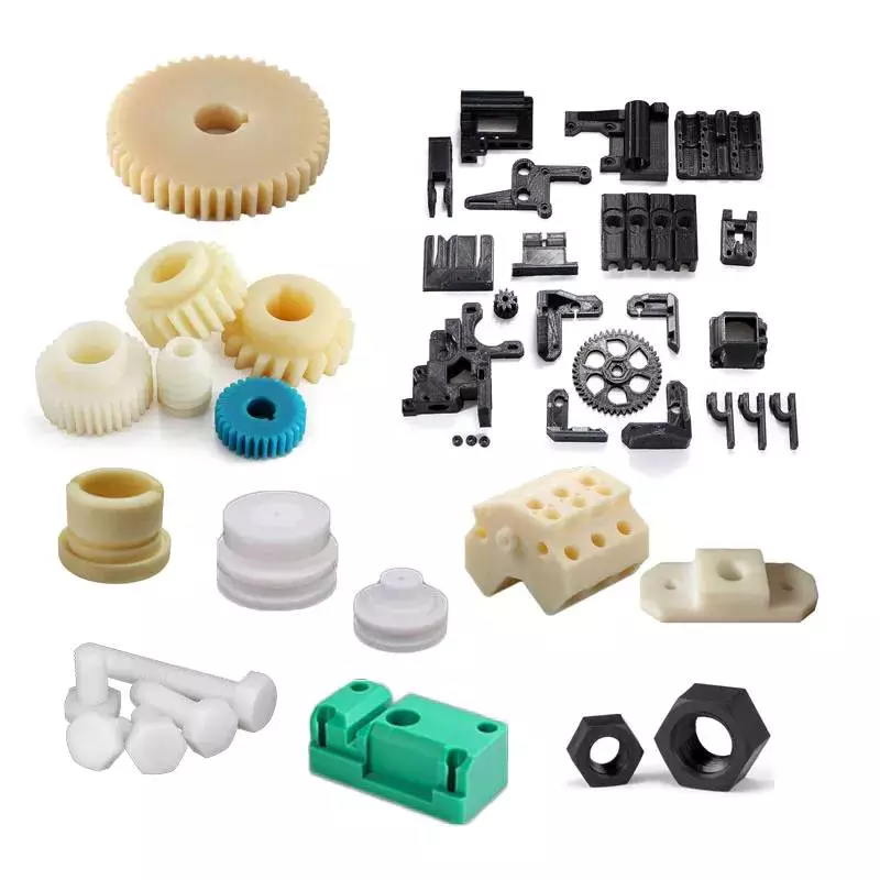 Injection molded parts often use fasteners for securing fastener elements in place. As shown in FIGS. 7 and 8 (two separate views), the fastener elements are integrated with the molded product, and they extend from one side. The fastener elements are designed to engage loop elements in the overlying layer. The palm-tree shaped fasteners are especially well-suited for this purpose, as their three-dimensional sides engage more loops than flat sides. These features result in a more secure closure.
When fasteners are used in injection molded parts, the plastic is injected into a mold, with the fastener integrated. In addition to self-tapping screws, other plastic fasteners can include moulded or pre-drilled pilot holes. This method avoids the need for a secondary assembly step and ensures an easy fit. These screws also have other advantages, including a smaller thread profile and lower radial stress, which prevents boss damage.
Another type of fastener commonly used in injection molded parts is a boss. This type of fastener is typically larger than the nut and the pilot hole. An undersized boss can lead to warpage during the injection molding process and cause a product to fail in the field.
Another type of fastener used in injection molded parts is a thread insert, which is usually a stainless steel A2 wire. There are different versions of this fastener for different materials, including carbon fiber reinforced plastic. And the fastener can be modified to adjust the size of the hole.
These fasteners are used in many different types of injection molded parts. Some parts are used to fix a variety of cosmetic issues, such as minor sinks. While these are not defects, they may not look perfect, and they can affect the overall appearance of a product. If you want to improve the appearance of an injection molded part, you can add fibers and glass fibers, as well as colorants.
editor by CX 2023-06-08
China Custom Dongguan ISO Manufacture High-precision 5 axis agricultural machinery parts cnc machining service agricultural parts UK
CNC Machining or Not: Cnc Machining
Type: Broaching, DRILLING, Etching / Chemical Machining, Laser Machining, Milling, Other Machining Services, Turning, Wire EDM, Rapid Prototyping
Substance Capabilities: Aluminum, Brass, Bronze, Copper, Hardened Metals, Precious Metals, Stainless Steel, Steel Alloys
Micro Machining or Not: Micro Machining
Materials: Aluminum/Steel/Brass/ iron/Zinc alloy and so forth.
Method: CNC Turning/Milling/Grinding/Slicing/Drilling/Punching /Welding
Surface treatment method: Anodizing/sandblasting/Galvanizing/Plating/Brushing/Polishing and so on
Provider: OEM ODM Custom-made
Tolerance: .005-.01mm
Drawing Format: STP/Action/IGS/PRT/X_T
MOQ: 1-10PCS
Lead time: 7 – 15days
Gear: 3/4/5 Axis Center Machining
Key word: Customized cnc machining
Packaging Specifics: Clear bag &thick epe &3-layer corrugated box &wood box. 1. Every carton weighs no a lot more than 20kg.2.Thick epe to avert crash injury.
Port: HangZhou
Certifications Products Description
| CNC Machining Technical specs | ||
| Pros | Description | |
| Tolerance | +/-.01mm, 100% QC quality inspection ahead of shipping and delivery, can provide top quality inspection kind | |
| Processing | CNC Turning, Milling, drilling, auto lathe, tapping, bushing, surface remedy, and many others. | |
| Material | Aluminum, copper, brass, stainless metal, metal, 8 spline pto shaft agriculture devices components iron, alloy, zinc and many others. Other Unique Components:Lucite/Nylon/wood/titanium/and so on | |
| Surface remedy | Anodizing, Brushing, Galvanized, laser engraving, Silk printing, polishing, Powder coating and many others. | |
| Color | White, black,silver, red, gray, Pantone and RAL, and so forth | |
| Pricing Phrase | EXW, FOB,CIF, and so on | |
| Payment phrase | Sample: 100% payment ahead of manufacturing Mass creation: (50% in advance as deposit,balance before shipping) | |
| Lead-time | 7days for prototype 15days for production | |
| CNC Milling Turning drilling Lathe Machining Processing manufacture fabrication manufacturing unit price tag. | ||
How to Calculate the Diameter of a Worm Gear

In this article, we will discuss the characteristics of the Duplex, Single-throated, and Undercut worm gears and the analysis of worm shaft deflection. Besides that, we will explore how the diameter of a worm gear is calculated. If you have any doubt about the function of a worm gear, you can refer to the table below. Also, keep in mind that a worm gear has several important parameters which determine its working.
Duplex worm gear
A duplex worm gear set is distinguished by its ability to maintain precise angles and high gear ratios. The backlash of the gearing can be readjusted several times. The axial position of the worm shaft can be determined by adjusting screws on the housing cover. This feature allows for low backlash engagement of the worm tooth pitch with the worm gear. This feature is especially beneficial when backlash is a critical factor when selecting gears.
The standard worm gear shaft requires less lubrication than its dual counterpart. Worm gears are difficult to lubricate because they are sliding rather than rotating. They also have fewer moving parts and fewer points of failure. The disadvantage of a worm gear is that you cannot reverse the direction of power due to friction between the worm and the wheel. Because of this, they are best used in machines that operate at low speeds.
Worm wheels have teeth that form a helix. This helix produces axial thrust forces, depending on the hand of the helix and the direction of rotation. To handle these forces, the worms should be mounted securely using dowel pins, step shafts, and dowel pins. To prevent the worm from shifting, the worm wheel axis must be aligned with the center of the worm wheel’s face width.
The backlash of the CZPT duplex worm gear is adjustable. By shifting the worm axially, the section of the worm with the desired tooth thickness is in contact with the wheel. As a result, the backlash is adjustable. Worm gears are an excellent choice for rotary tables, high-precision reversing applications, and ultra-low-backlash gearboxes. Axial shift backlash is a major advantage of duplex worm gears, and this feature translates into a simple and fast assembly process.
When choosing a gear set, the size and lubrication process will be crucial. If you’re not careful, you might end up with a damaged gear or one with improper backlash. Luckily, there are some simple ways to maintain the proper tooth contact and backlash of your worm gears, ensuring long-term reliability and performance. As with any gear set, proper lubrication will ensure your worm gears last for years to come.
Single-throated worm gear
Worm gears mesh by sliding and rolling motions, but sliding contact dominates at high reduction ratios. Worm gears’ efficiency is limited by the friction and heat generated during sliding, so lubrication is necessary to maintain optimal efficiency. The worm and gear are usually made of dissimilar metals, such as phosphor-bronze or hardened steel. MC nylon, a synthetic engineering plastic, is often used for the shaft.
Worm gears are highly efficient in transmission of power and are adaptable to various types of machinery and devices. Their low output speed and high torque make them a popular choice for power transmission. A single-throated worm gear is easy to assemble and lock. A double-throated worm gear requires two shafts, one for each worm gear. Both styles are efficient in high-torque applications.
Worm gears are widely used in power transmission applications because of their low speed and compact design. A numerical model was developed to calculate the quasi-static load sharing between gears and mating surfaces. The influence coefficient method allows fast computing of the deformation of the gear surface and local contact of the mating surfaces. The resultant analysis shows that a single-throated worm gear can reduce the amount of energy required to drive an electric motor.
In addition to the wear caused by friction, a worm wheel can experience additional wear. Because the worm wheel is softer than the worm, most of the wear occurs on the wheel. In fact, the number of teeth on a worm wheel should not match its thread count. A single-throated worm gear shaft can increase the efficiency of a machine by as much as 35%. In addition, it can lower the cost of running.
A worm gear is used when the diametrical pitch of the worm wheel and worm gear are the same. If the diametrical pitch of both gears is the same, the two worms will mesh properly. In addition, the worm wheel and worm will be attached to each other with a set screw. This screw is inserted into the hub and then secured with a locknut.
Undercut worm gear
Undercut worm gears have a cylindrical shaft, and their teeth are shaped in an evolution-like pattern. Worms are made of a hardened cemented metal, 16MnCr5. The number of gear teeth is determined by the pressure angle at the zero gearing correction. The teeth are convex in normal and centre-line sections. The diameter of the worm is determined by the worm’s tangential profile, d1. Undercut worm gears are used when the number of teeth in the cylinder is large, and when the shaft is rigid enough to resist excessive load.
The center-line distance of the worm gears is the distance from the worm centre to the outer diameter. This distance affects the worm’s deflection and its safety. Enter a specific value for the bearing distance. Then, the software proposes a range of suitable solutions based on the number of teeth and the module. The table of solutions contains various options, and the selected variant is transferred to the main calculation.
A pressure-angle-angle-compensated worm can be manufactured using single-pointed lathe tools or end mills. The worm’s diameter and depth are influenced by the cutter used. In addition, the diameter of the grinding wheel determines the profile of the worm. If the worm is cut too deep, it will result in undercutting. Despite the undercutting risk, the design of worm gearing is flexible and allows considerable freedom.
The reduction ratio of a worm gear is massive. With only a little effort, the worm gear can significantly reduce speed and torque. In contrast, conventional gear sets need to make multiple reductions to get the same reduction level. Worm gears also have several disadvantages. Worm gears can’t reverse the direction of power because the friction between the worm and the wheel makes this impossible. The worm gear can’t reverse the direction of power, but the worm moves from one direction to another.
The process of undercutting is closely related to the profile of the worm. The worm’s profile will vary depending on the worm diameter, lead angle, and grinding wheel diameter. The worm’s profile will change if the generating process has removed material from the tooth base. A small undercut reduces tooth strength and reduces contact. For smaller gears, a minimum of 14-1/2degPA gears should be used.
Analysis of worm shaft deflection
To analyze the worm shaft deflection, we first derived its maximum deflection value. The deflection is calculated using the Euler-Bernoulli method and Timoshenko shear deformation. Then, we calculated the moment of inertia and the area of the transverse section using CAD software. In our analysis, we used the results of the test to compare the resulting parameters with the theoretical ones.
We can use the resulting centre-line distance and worm gear tooth profiles to calculate the required worm deflection. Using these values, we can use the worm gear deflection analysis to ensure the correct bearing size and worm gear teeth. Once we have these values, we can transfer them to the main calculation. Then, we can calculate the worm deflection and its safety. Then, we enter the values into the appropriate tables, and the resulting solutions are automatically transferred into the main calculation. However, we have to keep in mind that the deflection value will not be considered safe if it is larger than the worm gear’s outer diameter.
We use a four-stage process for investigating worm shaft deflection. We first apply the finite element method to compute the deflection and compare the simulation results with the experimentally tested worm shafts. Finally, we perform parameter studies with 15 worm gear toothings without considering the shaft geometry. This step is the first of four stages of the investigation. Once we have calculated the deflection, we can use the simulation results to determine the parameters needed to optimize the design.
Using a calculation system to calculate worm shaft deflection, we can determine the efficiency of worm gears. There are several parameters to optimize gearing efficiency, including material and geometry, and lubricant. In addition, we can reduce the bearing losses, which are caused by bearing failures. We can also identify the supporting method for the worm shafts in the options menu. The theoretical section provides further information.


China Custom customized high precision machining color anodized service agricultural machinery small parts aluminium cnc milling parts with Hot selling
CNC Machining or Not: Cnc Machining
Type: Broaching, DRILLING, Etching / Chemical Machining, Laser Machining, Milling, Other Machining Services, Rapid Prototyping, Turning, Wire EDM
Substance Abilities: Aluminum, Brass, Bronze, Copper, Hardened Metals, Treasured Metals, Stainless Metal, Metal Alloys, custom-made
Micro Machining or Not: Micro Machining
Model Quantity: OEM
Merchandise: CNC Presicion Machining Part
Material: aluminium
MOQ: 1 Piece
Service: Customized OEM
Procedure: Cnc Turning
Area therapy: Coloration Anodize
Product name: Specialist Precision Cnc Machining Elements
Colour: Tailored Coloration
Tolerance: .005-.01
Our Services: Custom made Machining CNC Areas
Packaging Specifics: cnc shade anodized services machinery elements high pricision aluminum metal cnc partspacked in cartons inside,and wood situation outside the house.1. circumstances packed in wooden cases2. paper packaging 3. plastic packing 4. foam packaging Packaging in accordance to solution packaging or consumer needs.
Port: HangZhou
Our Primary Merchandise CNC machining of metal/aluminum/copper/and other metal areas Shade anodizing, zinc plating, nickel plating and polishing Personalized turning, milling, drilling, grinding, polishing and other components Products Description
| Material | 1. Stainless Steel: SS303, SS304, SS316, ss408,ss409,ss630, and so on.2. Metal: 12L14, 12L15, C45(AISI1045), Agricultural Tractor Spare Agriculture Machinery Components Casting and many others.3. Carbon Steel: CH1T, ML08AL, 1571, 1035, 1045, and so on.4. Alloy Metal: 10B21, 35ACR,40ACR, 40Cr, 35CrMn, and so forth.5. Aluminum or Aluminum Alloy: Al6061, Al6063, Al7075, and so on.6. Brass: C3604, C38000, and so on.We manage many other type of resources. Please speak to us if your required substance is not shown over. | ||||||
| Surface Therapy | Blacking/ Sharpening/ Anodizing/ Chrome plating/ Zinc plating/Nickel plating/ Chrome plating/tinting/and so on. | ||||||
| Process | Machining, Turning, milling, other process can be customized. | ||||||
| Standard | ISO, DIN, ANSI, JIS, BS and Non-standard | ||||||
| quality Manage | First inspection in each and every working procedure.Routing inspection in the machining generation.Entire inspection prior to shipment. | ||||||
| Drawing Format | IGS, X_T, Action, DWG, PDF, PNG, JPG | ||||||
| Terms Of Trade | EXW , FOB , CIF,and so forth. | ||||||
| Packing | Carton, R series inline helical equipment reducer gearbox for converter mixer Picket packing containers according to product packaging or customer requirements. | ||||||
How to Design a Forging Spur Gear
Before you start designing your own spur gear, you need to understand its main components. Among them are Forging, Keyway, Spline, Set screw and other types. Understanding the differences between these types of spur gears is essential for making an informed decision. To learn more, keep reading. Also, don’t hesitate to contact me for assistance! Listed below are some helpful tips and tricks to design a spur gear. Hopefully, they will help you design the spur gear of your dreams.
Forging spur gears
Forging spur gears is one of the most important processes of automotive transmission components. The manufacturing process is complex and involves several steps, such as blank spheroidizing, hot forging, annealing, phosphating, and saponification. The material used for spur gears is typically 20CrMnTi. The process is completed by applying a continuous through extrusion forming method with dies designed for the sizing band length L and Splitting angle thickness T.
The process of forging spur gears can also use polyacetal (POM), a strong plastic commonly used for the manufacture of gears. This material is easy to mold and shape, and after hardening, it is extremely stiff and abrasion resistant. A number of metals and alloys are used for spur gears, including forged steel, stainless steel, and aluminum. Listed below are the different types of materials used in gear manufacturing and their advantages and disadvantages.
A spur gear’s tooth size is measured in modules, or m. Each number represents the number of teeth in the gear. As the number of teeth increases, so does its size. In general, the higher the number of teeth, the larger the module is. A high module gear has a large pressure angle. It’s also important to remember that spur gears must have the same module as the gears they are used to drive.
Set screw spur gears
A modern industry cannot function without set screw spur gears. These gears are highly efficient and are widely used in a variety of applications. Their design involves the calculation of speed and torque, which are both critical factors. The MEP model, for instance, considers the changing rigidity of a tooth pair along its path. The results are used to determine the type of spur gear required. Listed below are some tips for choosing a spur gear:
Type A. This type of gear does not have a hub. The gear itself is flat with a small hole in the middle. Set screw gears are most commonly used for lightweight applications without loads. The metal thickness can range from 0.25 mm to 3 mm. Set screw gears are also used for large machines that need to be strong and durable. This article provides an introduction to the different types of spur gears and how they differ from one another.
Pin Hub. Pin hub spur gears use a set screw to secure the pin. These gears are often connected to a shaft by dowel, spring, or roll pins. The pin is drilled to the precise diameter to fit inside the gear, so that it does not come loose. Pin hub spur gears have high tolerances, as the hole is not large enough to completely grip the shaft. This type of gear is generally the most expensive of the three.
Keyway spur gears
In today’s modern industry, spur gear transmissions are widely used to transfer power. These types of transmissions provide excellent efficiency but can be susceptible to power losses. These losses must be estimated during the design process. A key component of this analysis is the calculation of the contact area (2b) of the gear pair. However, this value is not necessarily applicable to every spur gear. Here are some examples of how to calculate this area. (See Figure 2)
Spur gears are characterized by having teeth parallel to the shafts and axis, and a pitch line velocity of up to 25 m/s is considered high. In addition, they are more efficient than helical gears of the same size. Unlike helical gears, spur gears are generally considered positive gears. They are often used for applications in which noise control is not an issue. The symmetry of the spur gear makes them especially suitable for applications where a constant speed is required.
Besides using a helical spur gear for the transmission, the gear can also have a standard tooth shape. Unlike helical gears, spur gears with an involute tooth form have thick roots, which prevents wear from the teeth. These gears are easily made with conventional production tools. The involute shape is an ideal choice for small-scale production and is one of the most popular types of spur gears.
Spline spur gears
When considering the types of spur gears that are used, it’s important to note the differences between the two. A spur gear, also called an involute gear, generates torque and regulates speed. It’s most common in car engines, but is also used in everyday appliances. However, one of the most significant drawbacks of spur gears is their noise. Because spur gears mesh only one tooth at a time, they create a high amount of stress and noise, making them unsuitable for everyday use.
The contact stress distribution chart represents the flank area of each gear tooth and the distance in both the axial and profile direction. A high contact area is located toward the center of the gear, which is caused by the micro-geometry of the gear. A positive l value indicates that there is no misalignment of the spline teeth on the interface with the helix hand. The opposite is true for negative l values.
Using an upper bound technique, Abdul and Dean studied the forging of spur gear forms. They assumed that the tooth profile would be a straight line. They also examined the non-dimensional forging pressure of a spline. Spline spur gears are commonly used in motors, gearboxes, and drills. The strength of spur gears and splines is primarily dependent on their radii and tooth diameter.
SUS303 and SUS304 stainless steel spur gears
Stainless steel spur gears are manufactured using different techniques, which depend on the material and the application. The most common process used in manufacturing them is cutting. Other processes involve rolling, casting, and forging. In addition, plastic spur gears are produced by injection molding, depending on the quantity of production required. SUS303 and SUS304 stainless steel spur gears can be made using a variety of materials, including structural carbon steel S45C, gray cast iron FC200, nonferrous metal C3604, engineering plastic MC901, and stainless steel.
The differences between 304 and 303 stainless steel spur gears lie in their composition. The two types of stainless steel share a common design, but have varying chemical compositions. China and Japan use the letters SUS304 and SUS303, which refer to their varying degrees of composition. As with most types of stainless steel, the two different grades are made to be used in industrial applications, such as planetary gears and spur gears.
Stainless steel spur gears
There are several things to look for in a stainless steel spur gear, including the diametral pitch, the number of teeth per unit diameter, and the angular velocity of the teeth. All of these aspects are critical to the performance of a spur gear, and the proper dimensional measurements are essential to the design and functionality of a spur gear. Those in the industry should be familiar with the terms used to describe spur gear parts, both to ensure clarity in production and in purchase orders.
A spur gear is a type of precision cylindrical gear with parallel teeth arranged in a rim. It is used in various applications, such as outboard motors, winches, construction equipment, lawn and garden equipment, turbine drives, pumps, centrifuges, and a variety of other machines. A spur gear is typically made from stainless steel and has a high level of durability. It is the most commonly used type of gear.
Stainless steel spur gears can come in many different shapes and sizes. Stainless steel spur gears are generally made of SUS304 or SUS303 stainless steel, which are used for their higher machinability. These gears are then heat-treated with nitriding or tooth surface induction. Unlike conventional gears, which need tooth grinding after heat-treating, stainless steel spur gears have a low wear rate and high machinability.
China Custom Custom Fabrication Cnc Machining Aluminum Brass Stainless Steel Metal Agricultural Machinery Parts agricultural parts UK
CNC Machining or Not: Cnc Machining
Sort: DRILLING, Etching / Chemical Machining, Laser Machining, Milling, Other Machining Companies, Quick Prototyping, Turning, Wire EDM
Substance Capabilities: Aluminum, Brass, Bronze, Copper, Hardened Metals, Precious Metals, Stainless Steel, Metal Alloys, PL collection 60mm higher precision minimal back again lash tiny pace stepper ac motor planetary gearbox for wind turbine generator Other
Micro Machining or Not: Micro Machining
Design Number: RC036
Merchandise name: cnc rail
Packing: Customized Packing
Service: Personalized OEM
Keyword: oxicorte cnc element
MOQ: 1 Piece
OEM/ODM: Accecpted
Processing Type: cnc HangZhou
Colour: Custom-made Colour
Dimension: Tailored Size
Software: oxicorte cnc element
Packaging Information: cnc rail cnc HangZhou oxicorte cnc element
Port: HangZhou
Virtual Reality Showroom VR Items Description
| Model | Stainless Steel Capillary Tubes / Pipes |
| Standard | ASTM, ASME, EN, JIS, DIN, GB/YB BS NF, And so forth. |
| Material Grade | 304/0Cr18Ni9/X5CrNi18 9(1.4301)/ 304S15/Z6CN18-09/08X18H10(0X18H10)304L/00Cr18Ni10/X2CrNi18 9(1.4306)/ 304L12/Z2CN18-ten/03X18H11(000X18H11)316/0Cr17Ni12Mo2/X2CrNiMo18 ten(1.4401)/ Z6CND17-12316L/0Cr17Ni14Mo2/X2CrNiMo18 ten(1.4404)/ X2CrNiMo18 twelve(1.4435)/ 316S12/Z2CND17-12321, 409, 409L, 430 |
| Diameter | Outer Diameter: .1mm-eighty.mm |
| Wall Thickness: .05mm-2.0mm | |
| Length: ≤500mm Or in coil | |
| Tolerance | Outer Diameter: +/- .01mm |
| Thickness: +/- .01mm | |
| Length: +/- .1mm | |
| Surface Treatment method | Polishing, Annealing, Mirror area, Vibrant, Pickling |
| Type | Welded, Motor Tricycle Differential Gearbox Electric Rickshaw 48V 60V Motor Seamless |
| Shape | Round, Sq., Irregular |
| Application | medical therapy, petroleum, aerospace, health-related equipment, air conditioning, chemical industry, electronics, components, foodmachinery, electrical power generation, pharmaceutical, and other fields. |
| Packaging | In bundles with water-resistant substance, in picket casesPlease send specifics packing to us if you have other requirements |
How to Calculate the Diameter of a Worm Gear
In this article, we will discuss the characteristics of the Duplex, Single-throated, and Undercut worm gears and the analysis of worm shaft deflection. Besides that, we will explore how the diameter of a worm gear is calculated. If you have any doubt about the function of a worm gear, you can refer to the table below. Also, keep in mind that a worm gear has several important parameters which determine its working.
Duplex worm gear
A duplex worm gear set is distinguished by its ability to maintain precise angles and high gear ratios. The backlash of the gearing can be readjusted several times. The axial position of the worm shaft can be determined by adjusting screws on the housing cover. This feature allows for low backlash engagement of the worm tooth pitch with the worm gear. This feature is especially beneficial when backlash is a critical factor when selecting gears.
The standard worm gear shaft requires less lubrication than its dual counterpart. Worm gears are difficult to lubricate because they are sliding rather than rotating. They also have fewer moving parts and fewer points of failure. The disadvantage of a worm gear is that you cannot reverse the direction of power due to friction between the worm and the wheel. Because of this, they are best used in machines that operate at low speeds.
Worm wheels have teeth that form a helix. This helix produces axial thrust forces, depending on the hand of the helix and the direction of rotation. To handle these forces, the worms should be mounted securely using dowel pins, step shafts, and dowel pins. To prevent the worm from shifting, the worm wheel axis must be aligned with the center of the worm wheel’s face width.
The backlash of the CZPT duplex worm gear is adjustable. By shifting the worm axially, the section of the worm with the desired tooth thickness is in contact with the wheel. As a result, the backlash is adjustable. Worm gears are an excellent choice for rotary tables, high-precision reversing applications, and ultra-low-backlash gearboxes. Axial shift backlash is a major advantage of duplex worm gears, and this feature translates into a simple and fast assembly process.
When choosing a gear set, the size and lubrication process will be crucial. If you’re not careful, you might end up with a damaged gear or one with improper backlash. Luckily, there are some simple ways to maintain the proper tooth contact and backlash of your worm gears, ensuring long-term reliability and performance. As with any gear set, proper lubrication will ensure your worm gears last for years to come.
Single-throated worm gear
Worm gears mesh by sliding and rolling motions, but sliding contact dominates at high reduction ratios. Worm gears’ efficiency is limited by the friction and heat generated during sliding, so lubrication is necessary to maintain optimal efficiency. The worm and gear are usually made of dissimilar metals, such as phosphor-bronze or hardened steel. MC nylon, a synthetic engineering plastic, is often used for the shaft.
Worm gears are highly efficient in transmission of power and are adaptable to various types of machinery and devices. Their low output speed and high torque make them a popular choice for power transmission. A single-throated worm gear is easy to assemble and lock. A double-throated worm gear requires two shafts, one for each worm gear. Both styles are efficient in high-torque applications.
Worm gears are widely used in power transmission applications because of their low speed and compact design. A numerical model was developed to calculate the quasi-static load sharing between gears and mating surfaces. The influence coefficient method allows fast computing of the deformation of the gear surface and local contact of the mating surfaces. The resultant analysis shows that a single-throated worm gear can reduce the amount of energy required to drive an electric motor.
In addition to the wear caused by friction, a worm wheel can experience additional wear. Because the worm wheel is softer than the worm, most of the wear occurs on the wheel. In fact, the number of teeth on a worm wheel should not match its thread count. A single-throated worm gear shaft can increase the efficiency of a machine by as much as 35%. In addition, it can lower the cost of running.
A worm gear is used when the diametrical pitch of the worm wheel and worm gear are the same. If the diametrical pitch of both gears is the same, the two worms will mesh properly. In addition, the worm wheel and worm will be attached to each other with a set screw. This screw is inserted into the hub and then secured with a locknut.
Undercut worm gear
Undercut worm gears have a cylindrical shaft, and their teeth are shaped in an evolution-like pattern. Worms are made of a hardened cemented metal, 16MnCr5. The number of gear teeth is determined by the pressure angle at the zero gearing correction. The teeth are convex in normal and centre-line sections. The diameter of the worm is determined by the worm’s tangential profile, d1. Undercut worm gears are used when the number of teeth in the cylinder is large, and when the shaft is rigid enough to resist excessive load.
The center-line distance of the worm gears is the distance from the worm centre to the outer diameter. This distance affects the worm’s deflection and its safety. Enter a specific value for the bearing distance. Then, the software proposes a range of suitable solutions based on the number of teeth and the module. The table of solutions contains various options, and the selected variant is transferred to the main calculation.
A pressure-angle-angle-compensated worm can be manufactured using single-pointed lathe tools or end mills. The worm’s diameter and depth are influenced by the cutter used. In addition, the diameter of the grinding wheel determines the profile of the worm. If the worm is cut too deep, it will result in undercutting. Despite the undercutting risk, the design of worm gearing is flexible and allows considerable freedom.
The reduction ratio of a worm gear is massive. With only a little effort, the worm gear can significantly reduce speed and torque. In contrast, conventional gear sets need to make multiple reductions to get the same reduction level. Worm gears also have several disadvantages. Worm gears can’t reverse the direction of power because the friction between the worm and the wheel makes this impossible. The worm gear can’t reverse the direction of power, but the worm moves from one direction to another.
The process of undercutting is closely related to the profile of the worm. The worm’s profile will vary depending on the worm diameter, lead angle, and grinding wheel diameter. The worm’s profile will change if the generating process has removed material from the tooth base. A small undercut reduces tooth strength and reduces contact. For smaller gears, a minimum of 14-1/2degPA gears should be used.
Analysis of worm shaft deflection
To analyze the worm shaft deflection, we first derived its maximum deflection value. The deflection is calculated using the Euler-Bernoulli method and Timoshenko shear deformation. Then, we calculated the moment of inertia and the area of the transverse section using CAD software. In our analysis, we used the results of the test to compare the resulting parameters with the theoretical ones.
We can use the resulting centre-line distance and worm gear tooth profiles to calculate the required worm deflection. Using these values, we can use the worm gear deflection analysis to ensure the correct bearing size and worm gear teeth. Once we have these values, we can transfer them to the main calculation. Then, we can calculate the worm deflection and its safety. Then, we enter the values into the appropriate tables, and the resulting solutions are automatically transferred into the main calculation. However, we have to keep in mind that the deflection value will not be considered safe if it is larger than the worm gear’s outer diameter.
We use a four-stage process for investigating worm shaft deflection. We first apply the finite element method to compute the deflection and compare the simulation results with the experimentally tested worm shafts. Finally, we perform parameter studies with 15 worm gear toothings without considering the shaft geometry. This step is the first of four stages of the investigation. Once we have calculated the deflection, we can use the simulation results to determine the parameters needed to optimize the design.
Using a calculation system to calculate worm shaft deflection, we can determine the efficiency of worm gears. There are several parameters to optimize gearing efficiency, including material and geometry, and lubricant. In addition, we can reduce the bearing losses, which are caused by bearing failures. We can also identify the supporting method for the worm shafts in the options menu. The theoretical section provides further information.
China Standard Construction Agricultural Machinery Bulldozer Excavator Wheel Loader Spare Parts wholesaler
Item Description
Hub disk
Excellent value and original!
Supporting Ball Screws
In order to use a ball screw in a project, it is important to support it for rotation. Typically, this requires holding brackets and roller bearings. Longer screws may require bending or critical speed restraints. End machining may be necessary to fit the screw into the bearing. Connection to a motor requires coupling and appropriate machining. Tables or support rails may be necessary to restrain the nut.
Cost
In this report, you’ll get an in-depth analysis of the ball screw market. You’ll learn about the competitive landscape, product portfolio, and growth prospects across regions. The report will also include information on the market’s various drivers and restraints, as well as the factors driving or restraining its development. You’ll also get an in-depth look at the value chain and PEST analysis, which are important components of a market study.
One resource that you can use to research the Ball Screw market is CZPT. This website contains a database of authentic Indian manufacturers, suppliers, and importers. You’ll find contact details and email addresses of the companies, including those that produce a wide variety of different types of ball screws. CZPT even allows you to search by product category. That way, you can find a supplier based on the type of ball screw you need at the lowest price.
Another benefit of ball screws is their ability to operate in very delicate applications. In electric vehicles, they are often used to replace a common hydraulic system. They are also used to control gates at hydroelectric stations. You can also find them in motorised inspection tables, step photolithography machines, and microscopic integrated circuits. You can find hundreds of different ball screw designs, and you can even purchase them with nuts, wipers, and CZPT. Ball screws have several bearing balls, which help transfer load between nut and screw. They can be available with adjustable preload and non-preloaded options. And they’re manufactured to industry standards to meet the demands of their users.
If you’re looking for a reliable, high-performing screw, you’ll want to opt for a ball screw. These have high performance-to-cost ratios. You’ll need to choose between a lead screw and a ball screw, but both are reliable and efficient. Besides, the former is less expensive and offers great design flexibility. They’re corrosion-resistant and can even be self-locking for vertical applications.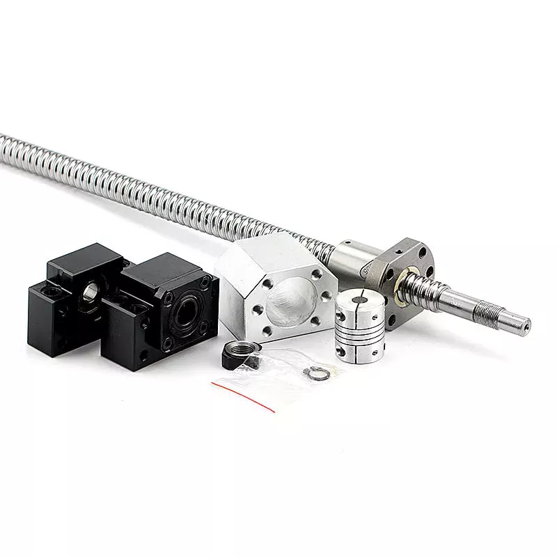
Applications
A ball screw and nut assembly are essential components of a variety of important actuation and control devices. The two components rely on the ability of the screw to rotate easily while converting the rotation into precise lateral movement. Ball screws are a common component in computer-controlled motion-control systems. The precision of ball screw rotation is essential for the accurate adjustment of flight control surfaces. In addition, ball screws are important components of wire bonding and computer-controlled motion-control systems.
Ball screws are highly accurate, requiring minimal lead error. The lead error of a screw is the difference between the theoretical and actual distance traveled by the nut during rotation. The lead error of a ball screw depends on several factors, including the manufacturing accuracy of the ball grooves, the compactness of the assembly, and the set-up precision. This error is not constant from lead to lead, but it may be reduced through preloading, lubrication, and increased mounting accuracy.
The ball is urged to move up and down by rotation of the nut, which is preferably a hexagonal shaft. This allows the ball to be raised easily over the land of the screw. It is important to note that the nut has a groove on the outer surface that is deep enough to accommodate a ball. This groove is deep enough to accommodate a ball, and the groove extends the length of the screw, thereby reducing friction and increasing precision.
The recirculated balls in a multi-start ball screw assembly may cross multiple threads and turn in the circuit. Multi-start ball screw assemblies typically use the internal channel method to recirculate balls. This design allows multiple ball nuts to be used in a single nut and can be easily installed. The ball nut and the nut may also be incorporated into several separate circuits. If several recirculation paths are desired, a ball nut and a multi-start system may be used.
Durability
A key feature of ball screws is their durability. During manufacture, a ball screw’s material must be chosen carefully. A corrosion-resistant steel called Cronidur(r) 30 is an ideal choice. Ball screws made from this material are exceptionally reliable in space due to their alternating steel-ceramic architecture. As the conditions of space are extreme, corrosion-resistant materials are essential to ensure optimum performance. CZPT has decades of experience manufacturing high-quality ball screws. Besides providing a complete range of ball screws, the company also offers technological solutions and dedicated components.
CZPT developed a special design for the High-Durability Precision Ball Screw. This design makes it easier to form a thin film of oil on the material’s surface. This oil helps reduce friction and improve the precision of a ball screw. This material’s special microstructure reduces the wear of ball screws and improves their service life. CZPT also aims to improve the wear-resistance of ball screws.
In addition to the axial load, a ball screw’s life rating should be based on the jacking and vertical loads. In other words, if all load balls are in contact with the raceways, the L-10 life rating of ball screw assemblies would be converted to an L-2 life rating. This change would increase the overall reliability of a ball screw to 98%. Then again, it’s important to note that vertical load is the only one that would be completely removed from the chart.
In addition to these important considerations, it is essential to operate ball screws within their recommended operating temperature range. Failure to do so could result in thermal expansion of the ball screw, causing positioning errors. To ensure lubrication of the ball screw, it’s important to keep its operating temperature within the recommended range. However, it is possible to operate it at temperatures that are too high. If this occurs, the screw should be sent to the manufacturer for repair.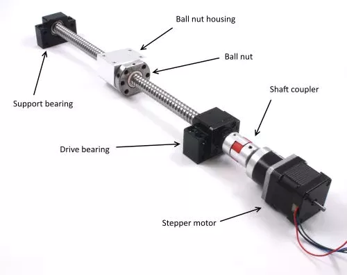
Size
Besides their obvious use, ball screws come in two sizes, large and small. Although small balls should not show significant wear, they should still be used to enhance the screw’s durability. This can be difficult to determine because screw rebuilders tend to overlook this aspect. So, what is the best size for ball screws? This article will look at both sizes and what they mean for the screw’s durability. Also, we’ll look at some of the things to keep in mind when choosing the right size for your project.
A ball screw’s size depends on its application and performance requirements. Some types have small diameters and fine leads, while others feature large diameters. High precision applications often require miniature ball screws. Some manufacturers even offer compact ball screws with a smaller outer diameter. The latter is commonly found in miniature designs and feature diameters up to 25 mm. However, this doesn’t mean that a smaller diameter means less accuracy. Regardless of the size, you’ll want to make sure to select a screw that will meet your requirements.
The screw’s root diameter is a critical measurement in determining critical speed and column load calculations. A ball screw’s minor diameter is the minimum dimension of the screw shaft at the bottom of the ball grooves. In addition, the idler ball is a necessary component of a ball screw. It prevents friction between the load and idler balls, but does not carry the load itself. Likewise, the non-operating load capacity should be large enough to prevent the balls from brinelling and plastic deformation.
The characteristic speed is the rotational speed at which the ball screw begins to vibrate due to dynamic load. Inch/imperial screws are specified for one million revolutions, while metric screw has a specific limit for 1 million inches of linear travel. Various manufacturing processes have their own ways to calculate the useful life of ball screw assemblies. For example, Precision Grinding produces the lowest lead errors. In addition, the life of a ball screw depends on the length of the screw and the mounting support for the end bearings.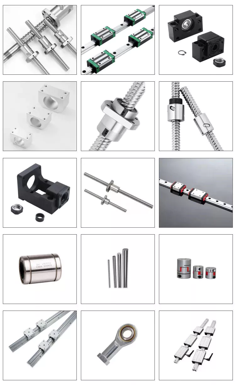
Maintenance
It is critical to regularly perform PM on your ball screw assemblies to ensure optimal performance. A dirty ball screw assembly will result in poor performance and faster wear, so removing dirt from the nut and shaft is a good idea. If there are problems with the ball nut, the lubricant inside can become stripped or the nut can become dirty due to chemical exposure. You should also check for oxidation or corrosion on the contact surfaces of the ball screw, and replace it if necessary.
The first sign of a deteriorating ball screw is excessive vibration. This may be caused by a bent screw shaft or misaligned bearing housings. If it makes noise when running, this may be due to excessive build-up or a broken return tube. Other issues may be caused by endplay in support bearings or excessive preload or improper lubrication. If any of these problems are found, it is essential to perform regular maintenance on the ball screw to prolong its life.
Getting regular maintenance on the ball screw assembly is important. If the screw is not properly maintained, it may wear out prematurely. If this happens, you can contact a ball screw repair service. CZPT International, Inc., a leading supplier of industrial parts, can help you get the screw back into optimal working order or find a new one. A ball screw repair company can help you avoid the inconvenience of downtime and maximize your productivity.
It is essential to properly lubricate a ball screw assembly in order to prolong its life. Lubrication can prevent corrosion and increase the life of the screw by 85 percent. It is important to remember that the type of lubricant you use should correspond to the load applied to the assembly. Lubrication should also be done at regular intervals. Once you’ve established the right amount of lubrication, you can then apply it on the screw.
China Hot selling Agricultural Machinery Parts CZPT tractor spare parts with Hot selling
Product Description
JINMA TRACTOR
Cultivate Your Dream
About US
- Began in 1959
- A countrywide backbone tractor manufacturer
- Company of tractor manufacturing was started out in 1969 (Much more than sixty years of historical past)
- Under ZheJiang CZPT Group Co., Ltd.
- A condition-holding business
- Main of the tractor generation enterprises
- Item export to North The united states, Europe, South America, Africa, southeast Asia and the Middle East spot about hundred countries and spot, The export amount is top 1 of same sector in china.
- The tractor Was voted as main cultivating international renowned manufacturers by ZheJiang section of commerce
Company Promotion
JINMA tractor is 1 of the world’s most well-liked tractor model. Largely which includes tractors covering sixteen-260HP, Solution exporting to far more than ninety countries and locations in North America, Europe, South The united states, Africa, Southeast Asia and the Middle East, the amount of export delivery benefit has been among the best of exact same market in China for numerous many years.CZPT has sturdy potential in establishing and planning products and best top quality administration system, effectively-equipped production tools, proudly owning pre-processing cathodic electrophoresis generation line, closing assembly line, and flexible processing line composed of Germany, Italy imported CNC, laser chopping device and welding robotconsisting of clever welding generation line. Have seasoned complex and management man or woman, our merchandise are novel design and style and tough in use. Our CZPT tractor has its personal mental property rights the goods have handed CE certification,EPA certification and get the patent. Insisting on high top quality stands, superior technologies and rational management, we acquire a excellent reputation amid our throughout the world buyers.
Solution Supply
FAQ
one. How can we ensure quality?
Always a pre-generation sample ahead of mass manufacturing
Often ultimate Inspection prior to shipment
two.What can you get from us?
Farm tractor Farm implements Farm equiment Spare areas.
three What solutions can we offer?
Accepted Shipping and delivery Terms: FOB,CIF
Recognized Payment Currency:USD,EUR
Recognized Payment Variety: T/T,L/C,
4.Guarantee Regulation of Merchandise Good quality
If Vendor market the tractor with CZPT manufacturer, The business will supply 24 months guarantee period to main components sell with OEM type twelve months warranty time period. The beginning date relies upon on service coverage.
| JINMA TRACTOR PASTS SUPPLY | |
| Engine Control Mechanism | Hood,Panel and Bracket |
| Double Clutch Assy (8") | Water tank,Air cleaner and Bracket |
| Front Axle | Mud Shield and Step |
| Front Axle | Electrical System Assy |
| Directive Wheel | Tool Box(option) |
| Front Driving Wheel | Fuel Tank |
| Driving Wheel | Hydraulic Steering and Pipe(2WD) |
| Pendulum drawbar | Hydraulic Steering and Pipe(4WD) |
| Drive Gearbox Cover | Hydraulic Power Lift |
| Drive Gearbox (Double speed 2WD) | Suspension Mechanism 1 |
| Drive Gearbox (Double speed 4WD) | Suspension Mechanism II |
| Creeper(2 WD) | Valve |
| Creeper(4 WD) | Brake and Operation Mechanism (Disc ) |
| Transfer Case For Front Drive | Brake and Operation Mechanism (Shoe) |
| Protective Structure | Seat |
Standard Length Splined Shafts
Standard Length Splined Shafts are made from Mild Steel and are perfect for most repair jobs, custom machinery building, and many other applications. All stock splined shafts are 2-3/4 inches in length, and full splines are available in any length, with additional materials and working lengths available upon request and quotation. CZPT Manufacturing Company is proud to offer these standard length shafts.
Disc brake mounting interfaces that are splined
There are two common disc brake mounting interfaces, splined and center lock. Disc brakes with splined interfaces are more common. They are usually easier to install. The center lock system requires a tool to remove the locking ring on the disc hub. Six-bolt rotors are easier to install and require only six bolts. The center lock system is commonly used with performance road bikes.
Post mount disc brakes require a post mount adapter, while flat mount disc brakes do not. Post mount adapters are more common and are used for carbon mountain bikes, while flat mount interfaces are becoming the norm on road and gravel bikes. All disc brake adapters are adjustable for rotor size, though. Road bikes usually use 160mm rotors while mountain bikes use rotors that are 180mm or 200mm.
Disc brake mounting interfaces that are helical splined
A helical splined disc brake mounting interface is designed with a splined connection between the hub and brake disc. This splined connection allows for a relatively large amount of radial and rotational displacement between the disc and hub. A loosely splined interface can cause a rattling noise due to the movement of the disc in relation to the hub.
The splines on the brake disc and hub are connected via an air gap. The air gap helps reduce heat conduction from the brake disc to the hub. The present invention addresses problems of noise, heat, and retraction of brake discs at the release of the brake. It also addresses issues with skewing and dragging. If you’re unsure whether this type of mounting interface is right for you, consult your mechanic.
Disc brake mounting interfaces that are helix-splined may be used in conjunction with other components of a wheel. They are particularly useful in disc brake mounting interfaces for hub-to-hub assemblies. The spacer elements, which are preferably located circumferentially, provide substantially the same function no matter how the brake disc rotates. Preferably, three spacer elements are located around the brake disc. Each of these spacer elements has equal clearance between the splines of the brake disc and the hub.
Spacer elements 6 include a helical spring portion 6.1 and extensions in tangential directions that terminate in hooks 6.4. These hooks abut against the brake disc 1 in both directions. The helical spring portion 5.1 and 6.1 have stiffness enough to absorb radial impacts. The spacer elements are arranged around the circumference of the intermeshing zone.
A helical splined disc mount includes a stabilizing element formed as a helical spring. The helical spring extends to the disc’s splines and teeth. The ends of the extension extend in opposite directions, while brackets at each end engage with the disc’s splines and teeth. This stabilizing element is positioned axially over the disc’s width.
Helical splined disc brake mounting interfaces are popular in bicycles and road bicycles. They’re a reliable, durable way to mount your brakes. Splines are widely used in aerospace, and have a higher fatigue life and reliability. The interfaces between the splined disc brake and BB spindle are made from aluminum and acetate.
As the splined hub mounts the disc in a helical fashion, the spring wire and disc 2 will be positioned in close contact. As the spring wire contacts the disc, it creates friction forces that are evenly distributed throughout the disc. This allows for a wide range of axial motion. Disc brake mounting interfaces that are helical splined have higher strength and stiffness than their counterparts.
Disc brake mounting interfaces that are helically splined can have a wide range of splined surfaces. The splined surfaces are the most common type of disc brake mounting interfaces. They are typically made of stainless steel or aluminum and can be used for a variety of applications. However, a splined disc mount will not support a disc with an oversized brake caliper.